
|
|
|
|
PASSWORD BASED ELECTRIC LOAD SWITCHING GEAR FOR THE SAFETY OF LINEMAN
Blessed Olalekan OYEBOLA*1
*1Department of Computer
Engineering Technology, Gateway (ICT) Polytechnic Saapade,
Nigeria
DOI: https://doi.org/10.29121/IJOEST.v1.i1.2017.05
ABSTRACT
Safety of human life is of a paramount importance. In high current switching system, switch gear protects electrical circuit. However there is need to provide confidence to working engineers during installation work on high voltage installations. To prevent accidental switching on of switch gear by unauthorized workforce, this paper proposed a more life secured switching password-enabled device that strengthen working confidence and inactivate unauthorized person from hazardous switching of electrical power installation without the notice of field working engineers.
Keywords: Electrical Power; Switching; Safety, Life; Password.
Cite This Article: Blessed Olalekan OYEBOLA. (2017). PASSWORD BASED ELECTRIC LOAD SWITCHING GEAR FOR THE SAFETY OF LINEMAN. International Journal of Engineering Science Technologies, 1(1), 48-55. doi: 10.29121/IJOEST.v1.i1.2017.05
1. INTRODUCTION
Safety of human life is of a paramount importance. In high current switching system, switch gear protects electrical circuit. ‘’Security is the prime concern in our day to day life. Everyone needs to be securing as much as possible. The electric line man safety system is designed to control a switch gear by using a password for the safety of electric man. Critical electrical accidents to line men are on the rise during electric line repair due to lack of communication and co-ordination between the maintenance staff and electric substation staff’’ [IEEE]. This paper offers a resolution that safeguards safety of maintenance line men. The control to turn on or off the line will be maintained by the line man only because this system has an arrangement such that a password is required to operate the circuit breaker (on/off) [National, 2002]. The system is fully controlled by a microcontroller from AVR family. A matrix keypad is interfaced to the microcontroller to enter the password. The entered password is compared with the password generated. If the password entered is correct, only then the line can be turned ON/OFF. To repair a particular section of the electric supply line or when the lineman wants to turn off the supply to a line, a request is first put forward to the system, and then the system responds to using the LCD display to enter the password. Then the system generates a password and it will be send to the processor. The password based switch gear can also be implemented in automatic door locking system for providing high security and also can be implemented to control electronic appliances to save the power.
Line Men Safety
System Description
The electric line man safety system provides a control to turn on or off the line and thereby ensures the safety of the staff [Pravinkumar N. M., 2016]. It consists of only an embedded section. The major component is a micro controller from AVR family.
Based on the program done in the microcontroller a relay switches to turn on or off the circuit breaker. The system comprised of LCD display, matrix keypad, and a relay. PIC15f887 microcontroller is used. Normally the supply to the line is always on and it is indicated by using a lamp which is always on. If there is any problem in any section of the supply line, then the line man wants to turn off the supply to that section and repair it. The LCD display provided along with the system gives visual assistance of “password based switch gear” for easy operation of the system. For that he first put a request to the system if the system is ready. The LCD display gives an indication of “SYSTEM READY” if is ready to work. Then, he put a request by pressing a switch.
This gives an indication to the system to turn off the supply to the line. Then the system generates a 4-bit length onetime password. And also gives an indication of “Password generated”. After enter it using the keypad, it will be compared with the generated password (which is stored in the ROM). If the passwords are matched, then the LCD displays “MATCHED” and turn off the supply to the line i.e, the lamp will be turned off. Therefore the line man can safely work on the line and repair it [Athira P. N., etal]. When repair is over, he will reach the substation and again put a request to turn on the supply by pressing the switch. Then system generates another password and using it he can turn on the line.
Password based
Switch gears As Switches
According to article by Brittian (1997) both the ANSI and the NEC definitions acknowledge the potential for the legitimate use of switch gears as switches. Switches (pass, but do not consume electrical energy) are considered as being control devices, thus one may also say that a breaker is a control device, or a controller. A password based switch gear can control and protect an electrical circuit and people operating the utilization equipment. An electrical relay is an example of an operating control; it opens and closes the circuit. Switch gears are not designed as replacements for operating controls such as relays, contactors, or motor starters. With the preceding enhancing our understanding, switch gears can legitimately be used as switches, though generally they are not intended for prolonged repetitive manual breaking and making type control of electrical energy utilization equipment.
2. OBJECTIVES
The aim of the project is to construct a prototype of password based switch gear that make use of four by four keyboard within the circuit to input password and LCD to display.
The major delinquent in the power system is the load
switching to prevent a hazardous shock to the line man. In this paper, password
based switch gear has been propose in switching of the load is done by the
lineman. Password protected switch gear
system is used to achieve more safety for a lineman during fault condition or
maintenance period. Switch gears are critical to the safe operation of an
electrical grid. They are needed in electricity generators, where the full
power of an entire power plant (gigawatts of electricity) must to be switched
on and off, and on transmission lines in substations to direct the power flow
at voltages in excess of 1500 kV. Switch gears are also critical components in
distribution grids, where very high currents need to be managed at moderate
voltage levels. A switch gear, irrespective of its position in a grid has two
tasks: it is responsible for the daily switching of lines during normal
operation, and for the disconnection of the power supply in case of overload or
short circuit.
3. SYSTEM DESIGN
The proposed system, Fig. 5, is concerned with the design and construction of a password based automatic change over. The proposed system ensures the security of the line man with the help of a protective password; we employed a microcontroller that accepts data from the interfacing circuit and take an instant decision. The propose system, Fig. 1, on putting the password through the matrix key board, opens or closes the line and also it can deny access to the line of the write password is not entered. These are the constituents of a password based switch gear.

Figure 1: Circuit diagram for password based switch gear
LCD Display
For ease of interaction with the user, this system uses an electronic display module. Here, Fig. 2, a 16x2 LCD is used. This means in two (2) lines it is possible to display 16 characters per line. A 5x8 pixel matrix is used for display one character. Two registers are associated with an LCD, such as data and command. These modules are preferred since it is easily programmable. For providing visual assistance to the lineman this module is unavoidable

Figure 2: LCD Display
Triac
Available in high power packages, the BTA/BTB40-41 series is suitable for the purpose of switching. They can be used as an ON/OFF fan.
Voltage Regulating
IC
A voltage regulator, Fig. 3, is designed to maintain a constant voltage level. A voltage regulator may use an electromechanical mechanism, or electronic components. Depending on design, it may be used to regulate one or more voltages. 7809 voltage regulating IC is used to provide the voltage 9V d.c.

Figure 3: Voltage Regulating IC
For the working of the system a power supply is needed. The micro controller needs only 5 Volt DC for its working. Therefore the incoming AC will be rectified, filtered and regulated by 7805 IC, Fig. 4.

Figure 4: Power section
Transformer
A transformer is electrical device that transfers the energy between two circuits through electromagnetic induction. A transformer may be used as a safe and efficient voltage converter to change the AC voltage at its input to a higher or lower voltage at its output. Other uses include current conversion, isolation with or without changing voltage and impedance conversion. It can also change the voltage level (lower to higher) and vice versa. Here in this project we are using it to step down the voltage level.
Resistor
The resistors act to reduce current flow, and, at the same time, act to lower voltage levels within circuits. Resistors may have fixed resistances or variable resistances, such as those found in thermistors trimmers, photo resistors and potentiometers. The current through a resistor is in direct proportion the voltage across the resistor’s terminals. This relationship is represented by Ohm's law: where I is the current through the conductor amperes, Vis the potential difference measured across the conductor in units of volts, and R is the resistance of the conductor in units of ohms(symbol: Ω). The ratio of the voltage applied across a resistor's terminals to the intensity of current in the circuit is called its resistance, and this can be assumed to be a constant (independent of the voltage) for ordinary resistor working with voltage.
Capacitor
A capacitor is an electrical device that can store energy in the electric field between a pair of closely-spaced conductors (called 'plates'). When voltage is applied to the capacitor, electric charges of equal magnitude, but opposite polarity, build up on each plate. Capacitors are used in electrical circuits as energy storage devices. They can also be used to differentiate between high-frequency and low-frequency signals and this makes them useful in electronic filters. Capacitors are occasionally referred to as condensers. This is now considered an antiquated term electrolytic capacitor. An electrolytic capacitor is a type of capacitor typically with a larger capacitance per unit volume than other types, making them valuable in relatively high current and low-frequency electrical circuits. This is especially the case in power-supply filters, where they store charge needed to moderate output voltage and current fluctuations, in rectifier output, and especially in the absence of rechargeable batteries that can provide similar low-frequency current capacity.
Microcontroller
Microcontroller is small computer on a single integrated circuit containing a processor, memory, and programmable input/output peripherals. Program memory in the form of NOR flash or OTP ROM is also often included on chip, as well as a typically small amount of RAM [Byreddy S. & Fazal, 2013]. Microcontrollers are designed for embedded applications, in contrast to the microprocessors used in personal computers or other general purpose applications.
Crystal oscillator
Crystal oscillator is an electronic oscillator circuit that uses mechanical resonance of a vibrating crystal of piezoelectric material to create an electrical signal with a very precise frequency. This frequency is commonly used to keep track of time to provide a stable clock signal for digital integrated circuits, and to stabilize frequencies for radio transmitters and receivers. The most common type of piezoelectric resonator used is the quartz crystal, so


Figure 5: Block diagram
The stages involved in the construction of the proposed system are: design validation, bread board and Vero-board implementations testing and packaging and modeling.
4. DESIGN VALIDATION
The best workable circuit was devised taking into consideration some parameters such signal levels between components, compatibility of signals and components, cost and availability of components. The program to direct the operation of the switch gear was written in C language and electronically written into PIC (16F887).
4.1.Vero-Board Implementation
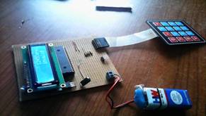
Figure 6: Vero
board implementation
After proper verification, the design was transferred to a vero board, Fig. 6, for permanent construction. The various module of the design were soldered and arranged on the vero board such that each module can be easily identified. Before proper soldering, component layout plan was drawn paying particular attention to minimizing the distance involve between point to be connected and the prevention of the overcrowding. All other components were then connected up to implement the circuit.
4.2.Testing and Result
It is paramount important to establish a highly efficient testing techniques in other to minimize cost. Testing involve troubleshooting the hardware system to detect, isolate and correct internal or extern fault such as malfunction in the internal circuitry, input or output shorted to ground or Vcc input or output open circuited, short between two pins broken wire, poor of dry connection, bent or broken pins, or an IC and faulty ICs socket. The hardware system was properly tested because the software cannot work when the hardware is not functioning properly.
The testing of the entire circuit was carried out in stages
1) Each of the components was first tested using the multimeter in order to check for their state of performance and accurate values.
2) In connection of each component on the Vero-board was then tested. This was done in other to carry out the continuity, which is meant for proper connection of the circuit and to detect any wrong connection.
3) The microcontroller unit circuitry was tested to ascertain the degree of sensitivity.
4.3.Packaging
After proper testing was conducted, the packaging, Fig. 7, of the design into a model and casing was considered. The connecting wires were properly connected and well insulated; also the wires were well packed and bounded together.

Figure 7: Password based electric load switching gear
Advantage of the Password Based Switch Gear
(i) It supports the safety of the lineman
(ii) It is very easy to construct
(iii) It does not require any mechanical services
(iv) It is easy to troubleshoot
5.
CONCLUSIONS AND
RECOMMENDATIONS
The electric line man safety system is designed to control a switch gear with help of a password only. Password based switch gear generation and Password based switch gear verification are the major tasks involved in this system. Password based switch gear generation is the main attraction of this project. It provides a new approach to the security of the lineman and completely eliminates the accidents to the lineman due to electric shock during the electric line repair. This system can also implement in many other public areas also.
Area of Applications
Password based switch gear can be used in distribution station to ensure the safety of linemen; it can be used at home or office to secure a particular room or device. It can be used in a genetic laboratory where very sensitive electricity is needed, and any other public area.
Future
Applications
Using wireless communication this system can be operated from other areas besides the substation such as on the transformer. The SCADA is a system used in the communication channels to help easy troubleshoot to locate the fault location directly and the line man can easily rectify it [Electirc, 2017]. The paper recommends for future development the password based switch gear should be GSM controlled, that will make the work more easer for the lineman.
REFERENCES
[1]
Athira P Nair, Josephin J, Anjana
A S, Athira C P and Sebin J
Olickal. (2015). Electric Line Man Safety System With OTP Based Circuit Breaker. IJRET: International Journal
of Research in Engineering and Technology eISSN:
2319-1163 | pISSN: 2321-7308. Volume: 04 Special
Issue: 03. Retrieve from: http://www.ijret.org
[2]
Brittian L. W., 1997. National Electrical Safety Code.
[3]
Byreddy Swetha and Dr. Fazal Noor basha. (2013). “A Low Power
Controlling Processor Implementing in SOC” International Journal of Engineering
Trends and Technology (IJETT) - Volume4 Issue7.
ISSN: 2231-5381. Retrieved from: www.ijettjournal.org
[4]
Electric Line Man
Safety System With Otp Based Circuit Breaker”.
www.Academia.Edu/.../Electric_Line_Man_Safety_Sys.
[5]
IEEE Engineering
in Medicine and
Biology Magazine,1996, 116-120, 15(2):106-110
[6]
National
Electrical Safety Code Committee, 2002.
Accredited Standards Committee C2 Rule 441 Table 441-1 AC Live Work
Minimum Approach Distance, page 228
[7]
Pravinkumar N.Mahadik, Mr. Pratik A.Yadav, Mr. Suraj B. Ghotpagar
and Harsha P. Pawar. (2016). “Electric Line Man Safety using Micro
Controller with GSM Module”
[8]
IJSRD -
International Journal for Scientific Research & Development. Vol. 4, Issue
01, ISSN (online): 2321-0613. Retrieved from: www.ijsrd.com

|
|
 This work is licensed under a: Creative Commons Attribution 4.0 International License
© IJOEST 2016-2020. All Rights Reserved.