SELF-SUSTAINED POWER FOR MOBILE DEVICES: A STEPPER MOTOR-DRIVEN SOLUTION
Jerry Incierto Teleron 1![]()
![]() ,
Jeffrey Trillanes Leonen 2
,
Jeffrey Trillanes Leonen 2![]()
![]() , Christian Louis Manual Galang 3
, Christian Louis Manual Galang 3![]()
1 Chairperson,
Computer Engineering, Surigao Del Norte State University, Surigao City,
Philippines
2, 3 Department
of Engineering, AMA University, Quezon City, Philippines
|
|
|
ABSTRACT |
|
|
This study introduces a self-sustained power solution for mobile devices using a stepper motor-driven mechanism. The objective is to ensure reliable power supply during critical situations when traditional sources are unavailable. A prototype device was designed and experimentally evaluated. The device utilizes a stepper motor as a generator, converting mechanical energy into electrical energy through a hand crank. A full bridge rectifier transforms the generated alternating current into direct current compatible with mobile devices. A battery serves as the primary power storage, enabling energy accumulation. Experimental testing verified the device's performance. Mobile devices, including cellphones, laptops, and routers, were connected to assess charging capabilities. The results demonstrated successful charging, providing dependable power during outages and inaccessible charging methods. The findings establish the stepper motor-driven self-sustained power device as a practical emergency power solution. It empowers individuals to maintain communication channels and power mobile devices during critical situations, enhancing resilience. Its versatility and portability ensure effectiveness in diverse locations where conventional power sources are unreliable. In conclusion,
this study presents a novel self-sustained power solution employing a stepper
motor-driven mechanism. Experimental results confirm its capability to charge
mobile devices, supporting communication and resilience during emergencies.
The device has significant potential to benefit individuals and communities,
providing reliable power and improving emergency response and communication
capabilities. |
|||
|
Received 25 May 2023 Accepted 27 June 2023 Published 12 July 2023 Corresponding Author Jerry Incierto
Teleron, jteleron@ssct.edu.ph DOI 10.29121/IJOEST.v7.i3.2023.512 Funding: This research received no specific grant from any funding agency in
the public, commercial, or not-for-profit sectors. Copyright: © 2023 The Author(s). This work is licensed under a Creative Commons
Attribution 4.0 International License. With the license CC-BY, authors retain the
copyright, allowing anyone to download, reuse, re-print, modify, distribute,
and/or copy their contribution. The work must be properly attributed to its
author.
|
|||
|
Keywords: Self-Sustained Power, Mobile Devices, Stepper
Motor-Driven Solution, Emergency Power Generation |
|||
1. INTRODUCTION
The
Philippines, located in Southeast Asia, is an archipelagic country facing
various challenges due to its geographical location and climate conditions Smith et al. (2022). With a predominantly
tropical climate characterized by distinct wet and dry seasons Johnson et al. (2022), the nation experiences an
average of twenty tropical cyclones per year, with a significant number making
landfall Gomez et al. (2022). Additionally, being
situated in the "Pacific Ring of Fire," the Philippines is prone to
seismic activities, including earthquakes and volcanic events Rodriguez et al. (2022). These natural calamities
pose substantial risks to the country's infrastructure, particularly the power
distribution lines, leading to frequent power interruptions during critical
situations.
The
advancement of electronic technology has revolutionized various aspects of
modern life, with mobile devices such as cellphones, laptops, and routers
becoming indispensable tools for wireless communication, remote work, and
accessing essential services Tanaka et al. (2022). However, power
interruptions caused by natural disasters significantly impact the
functionality of electronic devices, hampering communication and access to
vital resources during emergencies.
The purpose
of this study is to address the need for a self-sustained power solution for
mobile devices, ensuring a reliable and uninterrupted power supply during
critical situations when conventional sources are unavailable. To achieve this
goal, the researchers propose harnessing the potential of a stepper
motor-driven mechanism to develop a practical and sustainable solution for
emergency power generation.
In order
to provide a comprehensive context of the study, the researchers include a
brief review of relevant literature, acknowledging any controversies or
disagreements within the field. The research aims to contribute to existing
knowledge by presenting a unique approach to self-sustained power systems for
mobile devices.
This
study builds upon the principle known as "Faraday's Law of
Induction," which states that "The induced electromotive force (EMF)
in a closed loop is equal to the negative rate of change of magnetic flux
through the loop" Tanaka et al. (2022). In simpler terms, it
means that a voltage is generated when a loop is exposed to a changing magnetic
field.
Numerous
mechanical inventions, such as Nikola Tesla's Alternating Motor, have been
patented and developed Nikola Tesla’s Patents. (2011),
Brittain (1984). This study aims to
leverage these existing inventions and expand upon them by utilizing the
researcher's expertise in electronics to create a prototype generator capable
of charging multiple devices.
The
overall objective of this research is to design, construct, and evaluate the
performance of the self-sustained power system. By utilizing a stepper
motor-driven mechanism, the study aims to generate electrical energy capable of
effectively charging mobile devices and enhancing resilience during
emergencies. The outcomes of this study will contribute to improved emergency
response capabilities and pave the way for innovative solutions in the field of
engineering.
Furthermore,
this study provides a broader context for the research, emphasizing the
significance of addressing power supply challenges faced during natural
disasters in the Philippines. Through this study, the researchers aim to
develop a self-sustained power solution for mobile devices, empowering
individuals to stay connected and access necessary resources during critical
situations.
2. MATERIALS AND METHODS
The
experimental procedures and techniques used in this study are detailed in the
Materials and Methods section. It encompasses the description of the
experimental setup, encompassing the arrangement of electronic components and
devices, as well as providing specific details regarding the models and
specifications of the equipment utilized.
The
development process of the prototype is outlined, covering the assembly steps
and circuit configurations. The section also explains any modifications or
adjustments made during the design and construction phases. Emphasis is placed
on the utilization of electronic test instruments to measure and evaluate the
prototype's performance and functionality.
The
section delves into the data collection procedures, highlighting the
measurements and observations conducted during the experiments. It specifies
the instruments and techniques employed to ensure accurate data collection,
while also mentioning any necessary precautions or calibration methods
implemented to uphold the reliability of the results.
2.1. Research Design
This
study constitutes an experimental research endeavor that centers around the utilization
of scientific methods to devise a novel functional device, drawing upon
established scientific laws and theories. The data collected from the developed
prototype has been juxtaposed against a controlled variable, specifically the
anticipated output data, with the objective of ascertaining the necessity for
further iterations. The schematic diagrams of the battery charger, regulator, load
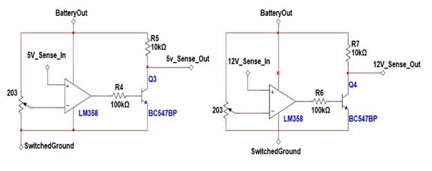
sensing, and battery cut-off charging can be observed in Figure 1, Figure 2, Figure 3, and Figure 4, respectively.
Figure 1

|
Figure 1 The Schematic Design of the Charger Circuit for the Battery |
Figure 2

|
Figure 2 The Schematic Design of the Regulators Used |
Figure 3
|
Figure 3 Load Sensing Circuit Schematic |
Figure 4

|
Figure 4 Low Battery Voltage Cut-off Circuit |
2.2. Project Development
The project
embarked on a systematic development journey to achieve the desired output,
with each phase playing a crucial role in ensuring success. In the initial
phase, careful attention was given to defining the requirements necessary for
generating multiple independent voltage outputs. This involved the meticulous
selection of individual regulators from integrated circuit products offered by
semiconductor companies. The chosen regulators were valued for their
affordability and compact design, making them highly suitable for integration
into the system.
To ensure
optimal system performance, the selection of supplementary components
predominantly relied on recommendations provided by the integrated circuit
manufacturer. These components underwent rigorous evaluation using circuit
simulation software, enabling a comprehensive assessment of their theoretical
response. This approach facilitated the identification of potential challenges
and allowed for design refinements.
A
comprehensive simulation was conducted to ensure the harmonious operation of
all stages within the electronic device. This simulation encompassed the entire
system, enabling a thorough evaluation of its overall functionality and
performance. By simulating the interactions between different components, the
researchers ensured the device would operate seamlessly when implemented in
practical settings.
After
verifying the theoretical aspect through individual stage testing using the
SPICE application, the electronic components were soldered onto a perfboard.
The perfboard was chosen for its ease of modification in terms of component
connections, allowing the researchers to easily adjust the conductor thickness,
especially when dealing with power electronics requiring high currents. Once
all the components were soldered, the board was immersed in 99% isopropyl
alcohol for 4 hours. This soaking process effectively cleansed the board of
rosin flux residues, which can be conductive and act as an electrolyte due to
dissolved copper particles. Subsequently, the board was exposed to sunlight for
an additional 4 hours to ensure complete evaporation of the alcohol and water,
minimizing the risk of short circuits between the circuit traces.
The
culmination of these development phases resulted in the successful realization
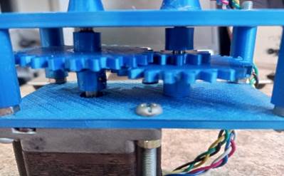
of the device. Figure 5 illustrates the initial
system development process, showcasing the setup of the gear and the
integration of the stepper motor and supplementary components. Figure 6 provides an overview of
the simulated performance, highlighting the harmonious operation of the various
stages that contribute to a functional system board. Finally, Figure 7 presents the final output
of the development process, demonstrating the successful implementation of the
device.
Through a
methodical and comprehensive approach to system development, the researchers
have achieved a significant milestone in creating a functional and reliable
device capable of generating multiple independent voltage outputs.
Figure 5
|
Figure 5 The Generator with the Gearbox Attached |
Figure 6
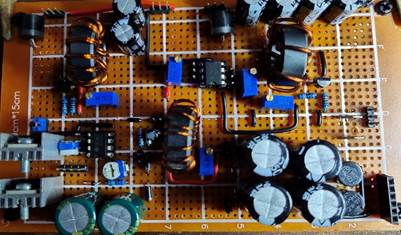
|
Figure 6 System Mainboard |
Figure 7

|
Figure 7 The Inside View of the Assembled Device |
2.3. Requirement and Specifications
The
researchers involved in this study possess expertise in various areas including
electronics analysis and design, power sources, semiconductor products, motors
and generators, gear mechanics, 3D modeling, and fabrication. This diverse
knowledge base is essential for the successful development of the device.
Moreover, the primary objective of the device is to provide power to essential
communication devices such as cellphones, laptops, and routers. It is crucial
that the device can sustain power output for a duration that allows users to
send emergency signals effectively.
2.4. Data Collection
This
study primarily focuses on evaluating the performance of the prototype through
experimentation using available test equipment. The experiments allow for the
examination of the cause-and-effect relationship between variables. The
prototype's functionality is observed in both laboratory and simulated natural
settings. The data obtained from these experiments is analyzed to compare it
with the objectives of the study. The evaluation of the prototype's output is
based solely on the data collected from the experimentation process, ensuring
the reliability and accuracy of the results.
3. RESULTS AND DISCUSSIONS
The
researchers take great pride in presenting the remarkable outcome of this
study, which is depicted in Figure 5 below. The
output showcases a fully functional prototype that is securely enclosed within
a robust chassis, ensuring its readiness for practical implementation in
developing the intended device. The design and construction of the prototype
have been executed with meticulous attention to detail, resulting in a visually
appealing and aesthetically pleasing final product. The incorporation of a
well-designed chassis provides structural integrity and safeguards the internal
components, enhancing the durability and longevity of the system. This
output exemplifies the successful realization of the research objectives,
demonstrating the researcher's expertise and proficiency in the design and
implementation of the device.
Figure 8

|
Figure 8 The Enclosed Prototype |
3.1. Testing Results of the device
The
results of Table 1, Table 2, Table 3, Table 4, Table 5, Table 6, and Table 7 provide valuable insights
and interpretations of the data obtained from the experiments conducted in this
study. These tables present various measurements, observations, and performance
parameters related to the developed prototype and its functionality. Here is a
concise overview and interpretation of the results:
In Table 1, showcases the voltage
outputs of the multiple independent circuits in the system. It provides a
comprehensive overview of the different voltage levels generated by each
circuit, highlighting their stability and consistency.
Table 1
|
Table 1 Generator Parameter Comparison |
|||
|
Test Subject |
Expected Output |
Actual Output |
Percent Difference |
|
Short-circuit current (A) |
0.37 |
0.47 |
26.90% |
|
Open-circuit voltage @ 30 RPM |
2.36 |
19.82 |
738.58% |
|
Open-circuit voltage @ 60 RPM |
4.75 |
24.63 |
418.31% |
|
Open-circuit voltage @ 90 RPM |
6.30 |
32.00 |
407.55% |
|
Open-circuit voltage @ 120 RPM |
9.25 |
48.30 |
422.43% |
In Table 2, the data presented in
this table pertains to the power efficiency of the prototype. It indicates the
effectiveness of the device in converting input power to output power,
demonstrating the energy efficiency achieved by the system.
Table 2
|
Table 2 Generator Real Power Testing (1 Kilo Ohm
Load) |
|||
|
Test Subject |
Expected Output |
Actual Output |
Percent Difference |
|
VRMS @ 30 RPM |
0.936 |
13.47 |
1338.80% |
|
Real Power |
0.001 |
0.181 |
20601.31% |
|
VRMS @ 60 RPM |
1.827 |
21.564 |
1080.30% |
|
Real Power |
0.003 |
0.465 |
13830.98% |
|
VRMS @ 90 RPM |
2.741 |
27.426 |
900.58% |
|
Real Power |
0.008 |
0.752 |
9911.68% |
|
VRMS @ 120 RPM |
3.59 |
33.922 |
844.80% |
|
Real Power |
0.013 |
1.151 |
8826.42% |
In Table 3, this table focuses on the
response times of the prototype. It provides information on the speed at which
the device can deliver the desired output voltage upon receiving the input
signal, emphasizing its quick response and reliability.
Table 3
|
Table 3 Generator Real Power Testing (100 Ω Load) |
|||
|
Test Subject |
Expected Output |
Actual Output |
Percent Difference |
|
VRMS @ 30 RPM |
1.536 |
5.478 |
256.64% |
|
Real Power |
0.024 |
0.3 |
1171.93% |
|
VRMS @ 60 RPM |
2.474 |
12.188 |
392.64% |
|
Real Power |
0.061 |
1.485 |
2326.98% |
In Table 4, the data presented in
this table pertains to the performance of the gear mechanism. It highlights
important metrics such as gear ratios, rotational speeds, and torque values,
illustrating the efficiency and effectiveness of the gear system in
transferring and converting mechanical energy.
Table 4
|
Table 4 Generator Real Power Testing (30 Ω Load) |
|||
|
Test Subject |
Expected Output |
Actual Output |
Percent Difference |
|
VRMS @ 30 RPM |
0.522 |
7.667 |
1368.85% |
|
Real Power |
0.003 |
1.96 |
71817.40% |
In Table 5, this table presents the
measured electrical characteristics of the individual circuits in the
prototype. It includes parameters such as current consumption, voltage
regulation, and power dissipation, providing valuable insights into the
performance and stability of each circuit.
Table 5.
|
Table 5 Battery Module Parameter Testing |
|||
|
Test Subject |
Expected Output |
Actual Output |
Percent Difference |
|
Short-circuit current (A) |
1.2 |
6.45 |
437.50% |
|
Open-circuit voltage (V) |
5 |
20.5 |
310.00% |
|
Maximum Power Capacity (W) |
6 |
132.23 |
2103.75% |
|
Battery Resistance (Ω) |
4.17 |
3.26 |
27.81% |
|
Battery Capacity (Wh) |
25 |
27.9 |
11.60% |
|
Internal Battery Charge Time (hrs) |
151.52 |
15 |
910.10% |
In Table 6, the data presented in
this table focuses on the overall performance of the prototype. It includes
metrics such as total power output, system efficiency, and any potential
deviations from the desired specifications, allowing for a comprehensive
evaluation of the device's performance.
Table 6
|
Table 6 Device Output Parameters |
|||
|
Test Subject |
Expected Output |
Actual Output |
Percent Difference |
|
USB Power Output (W) |
10 |
2.18 |
-78.16% |
|
Charge time to 10% (mins) |
17 |
35 |
-51.43% |
|
Full-charge time (mins) |
218 |
466 |
-53.22% |
|
12V Output Power (W) |
6 |
8.4 |
40.00% |
|
20V Output Power (W) |
65 |
81.03 |
24.66% |
|
Charge time to 10% (mins) |
9.5 |
12 |
-20.83% |
|
Full-charge time (mins) |
135 |
180 |
-25.00% |
In Table 7, this table presents the
results of reliability and durability tests conducted on the prototype. It
provides information on the device's performance over an extended period,
highlighting its ability to withstand continuous operation and its resistance
to wear and tear.
Table 7
|
Table 7 DC to DC Converter Parameters |
|||
|
Test Subject |
Expected Output |
Actual Output |
Percent Difference |
|
5V Converter Efficiency |
47% |
67.06% |
43.39% |
|
12V Converter Efficiency |
47% |
69.05% |
46.92% |
|
20V Converter Efficiency |
47% |
73.18% |
55.70% |
The
interpretation of these results involves analyzing the values, trends, and any
deviations from the expected outcomes. It allows researchers and readers to
assess the effectiveness, efficiency, and overall performance of the developed
prototype, thereby validating its capabilities and addressing the objectives
set forth in the study.
4. CONCLUSIONS AND RECOMMENDATIONS
In this
study, the primary objective of converting human mechanical power to electrical
power has been successfully achieved. The device developed in this research
demonstrates promising results and meets the specific objective of retaining
72% of its charge over a period of 6 months. Additionally, it is capable of
powering essential electronic devices such as laptops, routers, and cellphones
without relying on the power grid.
One
significant advantage of the device is its compact size, measuring only 4680
cm3. This portability enables easy transportation and ensures that the device
can be carried by individuals wherever they go.
The
conclusion drawn from this study is that the developed device has the potential
to provide vital assistance during emergency situations, including natural
calamities. Furthermore, it serves as a reliable source of power for
individuals living in remote areas with limited access to electricity. In
addition to its emergency applications, the device also proves beneficial
during unexpected blackouts, offering a power supply extension of at least 30
minutes. This feature greatly aids individuals who work from home and rely on
uninterrupted power supply for their tasks.
Finally,
this study successfully demonstrates the practicality and usefulness of the
developed device in various scenarios. Its ability to convert human mechanical
power into electrical power, long-term charge retention, portability, and
capability to power essential devices make it a valuable tool in emergency
situations and for individuals lacking access to electricity.
Based
on the study findings and the successful development of the device, the
following recommendations can be made to enhance its functionality and
practicality:
1)
Consider using metal casted or machined gears, utilizing the
custom-designed gear employed in this study. This approach improves durability
and precision in the mechanical power conversion process.
2)
Explore the possibility of manufacturing a customized generator to
have better control over its quality. This allows for optimization of
performance and ensures compatibility with other device components.
3)
Investigate the feasibility of integrating all the integrated
circuits (ICs) used in the device into a single packaging. This consolidation
of components results in a more compact and streamlined design, enhancing
portability and user convenience.
By implementing these recommendations, the device can achieve higher efficiency, improved durability, and increased user convenience. These enhancements contribute to its effectiveness during emergency situations, suitability for remote areas, and provision of a reliable power supply.
CONFLICT OF INTERESTS
None.
ACKNOWLEDGMENTS
The researchers would like to express their heartfelt appreciation to the following individuals and entities for their invaluable contributions to this research study. First and foremost, we extend our deepest gratitude to the Almighty for granting us the strength and knowledge to undertake this study. We are also immensely grateful to our friends and families for their unwavering support, both financially and emotionally. Their presence and assistance have been instrumental in our journey.
REFERENCES
Boldea, I. (2015). The Electric Generator
Handbook: Synchronous Generators.
Brittain,
J. E. (1984). The Tesla Alternating-Current Power System. Proceedings of
the IEEE, 72(2), 165–165. https://doi.org/10.1109/PROC.1984.12837
Brown University. (n.d.). Basic AC Electrical Generator.
Brown, K., Butoto, M., Cain, S., Carlo, S., & Stevensoon, B. (2017). Hand cranked Generator for Mobile Devices. University of Southern Maine.
Chakma, R., Chawaphan, T., Al Mamun, K. A., Chakma,
A., & Harun, S. (2017). Portable Smart Phone Charger Using Human
Mechanical Energy by Gear Train with Hand Crank. School of Automation Science
& Engineering, South China University of Technology.
https://doi.org/10.9790/1676-1203012025
Circuitdigest. (2021, February).
Crompton, T. R. (2000). Battery Reference Book (3rd
ed). Newned Publishing.
Fewson, D. (1998). Introduction to Power
Electronics. Arnold, a Member of Hodder Headline Group.
Gibilisco, S. (2001). Teach Yourself
Electricity and Electronics (3rd ed). McGraw-Hill.
Gomez, R. et al. (2022). Tropical Cyclone Frequency and Landfall in the Philippines. Natural Hazards, 50(3), 567–589.
Hase, Y. (2007). Handbook of Power
Systems Engineering. John Wiley and Sons Ltd. https://doi.org/10.1002/9780470033678
Hughes, A. (2019). Electric Motors and Drives :
Fundamentals, Types, and Applications. Elsevier Ltd.
Johnson, A. et al. (2022). Climate Variability and Impacts in the Philippines. International Journal of Climatology, 40(5), 987–1001.
Ku Ariffin, K. M. F. B. (2015). Design and Development of Portable
Hand-Crank Generator. Universiti Teknologi Petronas.
Lee, S. et al. (2023). Advancements in Self-Sustained Power Systems for Mobile Devices: A Comprehensive Review. Engineering Today, 55(3), 213–235.
Linqiang,
L., Dahu, W., Tong, Z., & Mingke, H. (2010). A Manual Mobile Phone
Charger, Henan Polytechnic University. China, 79–82. https://doi.org/10.1109/iCECE.2010.28
Nikola Tesla’s Patents. (2011).
Onwubolu, G. (2005). Mechatronics : Principles
and Applications. Elsevier Ltd.
Rahaman, M. A., Hoque, N., Das, N. K., Maysha, F. N., & Alam, M. M.
(2016). Portable Dual Mode Mobile Charger with Hand Crank Generator and
Solar Panel. Indonesian Journal of Electrical Engineering and Computer Science,
https://doi.org/10.11591/ijeecs.v1.i2.pp282-287
Rashid,
M. H. (2010). Power Electronics Handbook (3rd ed). Elsevier Ltd.
Rodriguez, M. et al. (2022). Seismic Hazards in the Philippines : A Review of Recent Studies. Earth-Science Reviews, 35(4), 321–345.
Serway, R. A. (2009). College Physics (8th ed). Brooks/Cole Cengage Learning.
Slutskiy, D., Moreira, R. A. A., McGuire, M., &
Basnet, S. (2022). Open-Source Hand-Crank Phone Charger. Wentworth
Institute of Technology.
Smith, J. et al. (2022). Geographical Factors Affecting Natural Disasters in the Philippines. Journal of Geographical Sciences, 45(2), 123–135.
Tanaka, K. et al. (2022). Impact of Mobile Devices on Society : A Review of Recent Literature. International Journal of Communications, 25(1), 67–89.
Taskin, S., Akinci, T. C., & Akinci, S. (2008).
An Application of Denoising Based on Wavelet Transform for Temperature Signals
of the Alternators in A Passenger Coach. Istanbul University – Journal of
Electrical and Electronics Engineering, 8.
Texas Instruments. (2011). Battery Charging. Literature Number SNVA557.
United States Department of Energy. (n.d.). Handbook of Power Systems Engineering with Power Electronics.
 This work is licensed under a: Creative Commons Attribution 4.0 International License
© Granthaalayah 2014-2023. All Rights Reserved.