DEVELOPMENT OF HEATING AND COOLING THERMAL MODEL FOR AN AUTOMOTIVE AIR COMPRESSOR BASED ON EXPERIMENTAL DATA
Hao Liu 1![]()
![]() ,
Jae-Cheon Lee 2
,
Jae-Cheon Lee 2![]()
1 Assistant
Professor, Department of Mechanical Engineering, Keimyung University, Daegu (42601),
South Korea
2 Professor, Department of Mechanical Engineering, Keimyung University, Daegu (42601), South Korea
|
|
|
ABSTRACT |
|
|
The paper
presents how to determine the heating and cooling thermal model for an air
compressor of automotive air suspension system by using experimental data. A
set of test bench for the air compressor was firstly established. Based on
experiment, temperature of the heat sink of the air compressor and air
temperature and pressure inside two tanks were obtained. By analyzing heat
exchange process of air compressor, the thermal model of air compressor is
constructed, including temperature increasing and decreasing process. The
calculated results by means of the presented model show that the thermal model
can correctly descript the process of temperature variation of the air
compressor. |
|||
|
Received 20 March 2023 Accepted 23 April 2023 Published 08 May 2023 Corresponding Author Hao Liu, liuhao@kmu.ac.kr DOI 10.29121/IJOEST.v7.i3.2023.497 Funding: This research
received no specific grant from any funding agency in the public, commercial,
or not-for-profit sectors. Copyright: © 2023 The
Author(s). This work is licensed under a Creative Commons
Attribution 4.0 International License. With the
license CC-BY, authors retain the copyright, allowing anyone to download,
reuse, re-print, modify, distribute, and/or copy their contribution. The work
must be properly attributed to its author.
|
|||
|
Keywords: Air
Compressor, Air Suspension System, Thermal Model |
|||
1. INTRODUCTION
Usually, an air suspension system includes several components, such as an air compressor, air springs, auxiliary volumes, control valves, a reservoir, sensors, ECU, and so on Faisa (2005). Air compressor is used to provide compressed air to the air suspension system. Generally speaking, air compressor works in rigorous ambient in vehicle, because it is usually positioned near engine where there is high temperature. Moreover, its working pressure should be enough high to make air springs to suspend whole weight of vehicle, which means that lots of heat is produced when air compressor compresses air. Properties of temperature increasing and decreasing of the air compressor are quite significant in practice. As a result, this paper presents how to construct thermal models of an air compressor for vehicle by means of experimental data.
Remaining parts of the paper are arranged as below. The experiment is briefly described and measured data is presented in the section 2. And then, according to experimental results, temperature increasing and decreasing models are built, respectively, in the section 3 and 4. The last section gives some conclusions.
2. description of experiment
Figure 1
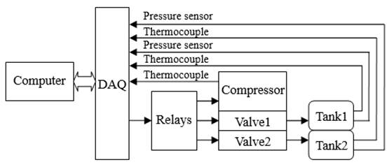
(a) Layout schematic
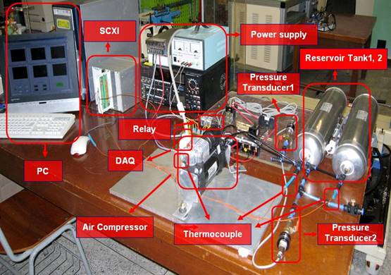
(b) Photo of test device
|
Figure 1 Schematic of Experiment |
The computer controls the air compressor to work or stop
by a relay and control air flow directions among the compressor and two tanks. First
of all, the compressor charges air into both tanks up to 9 bars. Next, the computer
controls two directional valves and the compressor to compress air from the
first tank to the second during 10 seconds, and then changes air charging
direction from the second tank to the first. The two valves shift air flow
direction every 10 second. A thermocouple is used to measure temperature on
heat sink of the air compressor. If compressor temperature exceeds 140 ℃,
the compressor will stop for cooling, while if compressor temperature reduces
less than 120℃, the compressor will run again and repeat charging air
between two tanks. Temperature rises and goes down totally 12 times between 120℃ and 140℃.
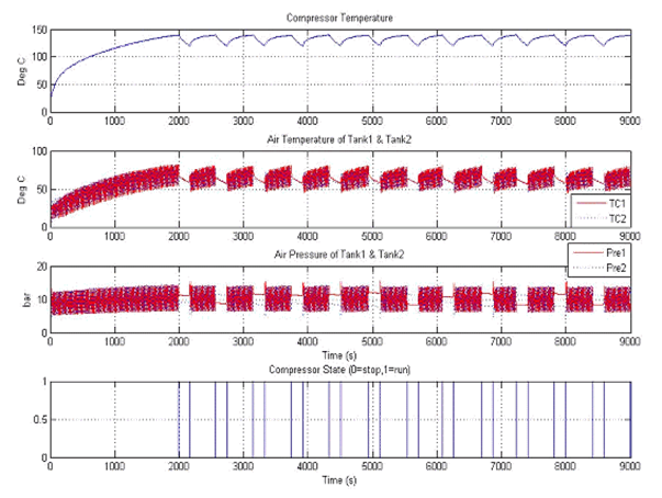
LabVIEW software is implemented to control the charging procedure and measure temperature and pressure. Figure 2 illustrates test results.
Figure 2
|
Figure 2 Experimental Results |
In order to obtain the thermal models of temperature increasing and decreasing durations, temperature increasing and decreasing durations are segmented, respectively, yielding 12 durations can be obtained. And then corresponding duration times of temperature increasing and decreasing are calculated and values as well as the average are listed in Table 1 and Table 2.
Table 1
|
Table 1 Time (sec) of Temperature Increasing from 120℃ to 140℃ |
|||||
|
402.6 |
412.5 |
412.6 |
412.5 |
431.7 |
422.7 |
|
372.2 |
432.2 |
362.9 |
412.3 |
422.9 |
401.7 |
Average: 408.32 second
Table 2
|
Table 2 Time (sec) of temperature decreasing from 140℃ to 120℃ |
|||||
|
172.8 |
174 |
176.7 |
176.2 |
175.7 |
179.9 |
|
173.6 |
173.5 |
178.6 |
173.4 |
178.3 |
174.6 |
Average: 175.61 second
3. Modeling of temperature increasing period
When the air compressor works, heat produced includes following three parts:
· Heat from compression of air
· Heat from the motor winding
· Heat from the valve winding
These three kinds of heat make compressor temperature increase quickly. However, it is very difficult to accurately describe these three kinds of heat by using analytical method. Amount of heat produced varies with different work conditions. Moreover, in the moment of heat production, heat dissipation occurs at the same time, which is effected by heat sink shape of compressor and ambient, such as temperature and convection condition. Heat production and dissipation together influence on compressor temperature Tang and Shi (2004). With time going, heat production and heat dissipation finally reach an equilibrium temperature.
If only convection is considered heat change ratio equals to sum of heat transfer and heat dissipation in unit time Cengel and Boles (2006), which can be expressed as following.
![]() Equation 1
Equation 1
Where
q: heat transfer per unit time
A: dissipation area
h: convection heat transfer coefficient
T: object temperature
Tamb: ambient temperature
For convenience, it is assumed that heat transfer per unit time to the air compressor is a constant because the compressor works in identical condition. Specific heat is defined as
![]() Equation 2
Equation 2
Therefore, combining Equation 1 andEquation 2, we can obtain
![]() Equation 3
Equation 3
By introducing two coefficients k1 and k2, the above equation can be rewritten as
![]() Equation 4
Equation 4
With the initial
condition ![]() , the solution of the differential Equation 4 is
, the solution of the differential Equation 4 is
![]() Equation 5
Equation 5
Where ![]() . It needs another two conditions to determine two
coefficients k2 and k. Consider following two conditions.
. It needs another two conditions to determine two
coefficients k2 and k. Consider following two conditions.
·
As t=408.32
second (the average of temperature ascending time of total), compressor
temperature is ![]() ℃.
℃.
·
As t=100
second, compressor temperature is ![]() ℃.
℃.
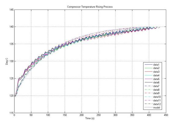
Finally, the compressor temperature ascending model is obtained as following with ambient temperature 23.2 ℃.
The experimental data and calculation results with using the model of Equation 6 are plotted in Figure 3.
Figure 3
|
Figure
3 Temperature Increasing Process
and its Simulation Result |
4. Modeling of temperature decreasing period
The Equation 1 describes cooling process if there is no heat transfer item. And also Newton Cooling Law Cengel and Boles (2006), Incropera and Dewitt (2001) is usually used to describe this process. It is stated that cooling ratio of an object is proportional to temperature difference between it and the ambient, as following mathematical expression.
![]() Equation
7
Equation
7
Where T is object temperature, Tamb is ambient temperature, and k is coefficient. This differential equation has solution as
![]() Equation 8
Equation 8
Considering the initial condition
![]() ℃,
℃, ![]() ℃, and
℃, and ![]() ℃.
℃.
The temperature decreasing model from
Plot the experimental data and calculation results with the model of Equation 9 in Figure 4.
Figure 4
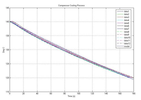
|
Figure
4 Temperature
Decreasing Process and its Simulation Rresult |
5. conlusions
Modeling of temperature variation of the air compressor for automotive air suspension system is complicated in that there are lots of factors to affect heat exchange. Moreover, some parameters are uncertain, which increases difficulties of accurate analysis. However, the temperature increasing and decreasing models are constructed based on the experimental data. Simulation results in Figure 3 and Figure 4 shows that only little bit difference exists between experimental temperature and that of simulation, which proof accuracy of the developed model. Our next work is that the wider temperature ranger should be consider further in order to completely investigate thermal property of the air compressor.
CONFLICT OF INTERESTS
None.
ACKNOWLEDGMENTS
None.
REFERENCES
Cengel, Y., Boles, M. (2006). Thermodynamics: an Engineering Approach (Fifth Edition), McGraw-Hill.
Faisa, B. (2005). Investigation of Switching Valve for Air-Spring Auxiliary Volumes by Means of Simulation With A Full Vehicle Model, Diplomarbeit, Institut fuer kraftfahrwesen Aachen.
Giuseppe, Q., & Massimo, S. (2001). Air Suspension Dimensionless Analysis and Design Procedure. Vehicle
System Dynamics, 35(6), 443-475, https://doi.org/10.1076/vesd.35.6.443.2040
Incropera, F., Dewitt, D. (2001). Fundamentals of Heat and Mass Transfer (Fifth Edition), John Wiley & Sons.
Tang, Y. Q., Shi, N. (2004). Electric Machinery (Second Edition), China Machine Press.
 This work is licensed under a: Creative Commons Attribution 4.0 International License
© Granthaalayah 2014-2023. All Rights Reserved.