SIMULATION AND ANALYSIS OF ELECTRO-OPTICAL CHARACTERISTICS OF ORGANIC COMPOUNDS IN ORGANIC LIGHT-EMITTING DIODES (OLEDS)
Imane EL Mhamedi 1![]()
![]() ,
Anass EL Karkri 1
,
Anass EL Karkri 1![]() , Zakaria EL Malki 1
, Zakaria EL Malki 1![]() , Mohammed Bouachrine 2
, Mohammed Bouachrine 2![]()
1 High
School of Technology, Moulay Ismail University, Meknes, Morocco
2 High School of Technology EST-Khenifra, Sultan Moulay Sliman University, Beni mellal, Morocco
|
|
|
ABSTRACT |
|
|
Organic light
emitters (OLEDs) work according to the principles of electroluminescence.
These OLEDs are commercially available and can be used in smartphone and
television displays due to their low power consumption, flexibility and
higher brightness than inorganic de-vices. The copolymer based on
3,4-ethylene dioxythiophene (EDOT) and poly(N-vinylcarbazole) (PVK) was
synthesized using previously published procedures. The copolymer was
synthesized by an oxidative copolymerization reaction, while the
DFT/B3LYP/6-31G(d,p) density function theory method was used to perform quantum
calculations. This paper presents the simulation results by SILVACO-TCAD
simulation software of the PVK-PEDOT organic matrix with calcium as cathode
and ITO as anode. The simulation is based on the distribution of the Langevin
recombination model including the proposed structure, and the electrical and
optical characteristics, such as current versus voltage, luminescence power,
and current versus electric field for different thicknesses, and charge
carrier densities of the emitting layer, as well as the I-V characteristics
for different temperature values. The model presented here will be useful in
the future for optimization of better electrical parameters. |
|||
|
Received 24 March 2023 Accepted 25 April 2023 Published 11 May 2023 Corresponding Author Imane EL
Mhamedi, elmhamedi@edu.umi.ac.ma DOI 10.29121/IJOEST.v7.i3.2023.496 Funding: This research
received no specific grant from any funding agency in the public, commercial,
or not-for-profit sectors. Copyright: © 2023 The
Author(s). This work is licensed under a Creative Commons
Attribution 4.0 International License. With the
license CC-BY, authors retain the copyright, allowing anyone to download,
reuse, re-print, modify, distribute, and/or copy their contribution. The work
must be properly attributed to its author.
|
|||
|
Keywords: Organic
Compounds, SILVACO, PVK-PEDOT, OLED, Electro-Optical Characteristics |
|||
1. INTRODUCTION
Currently, molecular materials based on π-conjugated
systems are in full development. These systems were discovered in the 1970s by
A. Hegger, Mc Diarmid and H. Shirakawa Heeger et al. (2002) during their research on doping
polyacetylene. Since then, many polymers and materials based on conjugated
compounds have been thoroughly investigated by several research teams Al-Azzawi et al. (2023).
Due to their physicochemical and optoelectronic properties, these systems are
being considered for various applications in the field of organic electronics.
Although the electroluminescence of organic materials was studied as early as
the 1960s thanks to the work of Pope and Helfrich Helfrich and Schneider (1965), it was not until
the 1980s that this phenomenon began to interest industrialists due to the rise
of organic electronics Partridge (1983).
Materials based on π-conjugated organic compounds
have attracted significant attention in the fields of chemistry, physics and
materials science Zeng et al. (2018).
This is due to their attractive characteristics, which include high charge
mobility, high throughput, lightness, flexibility, photochemical and thermal
stability Güney et al. (2019),
and the possibility of rapid and cost-effective roll-to-roll fabrication Raftani et al. (2021).
Indeed, this new discipline introduces organic materials
instead of classical inorganic semiconductors to realize organic light-emitting
diodes OLEDs, field effect transistors, photonic crystals, modulators, organic
solar cells (OSCs), optoelectronic components, lasers El karkri et al. (2022).
The first
OLED was created by Tang and Van Slyke in 1987 Luo et al. (2022).
Since this invention, OLEDs have continued to be studied and used for many
industrial applications. In 1987, Tang and Van Slyke created the first OLED, since
then OLEDs have been widely studied and used in many industrial applications. A
number of OLED-based applications are already being implemented, including the
production of thin and flexible TV displays, GPS navigation, portable media
players, radios, smartphones and clothing. A significant increase in production
volume is expected in the coming years as OLED lighting applications and printed
OLEDs enter the market Bizzarri
et al. (2018).
OLEDs are already used in models from Motorola, Samsung,
LG, Nokia and some models from Sony Ericsson Udhiarto et al. (2015).
OLEDs offer several advantages over competing technologies
such as LCDs and LEDs. First, OLEDs are relatively brighter, more flexible and
less expensive, while offering faster response than comparable devices. In
addition, OLEDs emit light directly at the pixel level, eliminating the need
for a backlight, unlike LCDs. This improves image quality in terms of color,
contrast and viewing angle, but more importantly, it allows for more compact
and lighter displays. This advantage is reinforced by the fact that OLED
technology is a thin film technology. The first OLED display commercialized by
LG in 2013 was no more than 4 mm thick for 3.5 kg.The compact and robust aspect
of OLEDs as well as the possibility of manufacturing the screen on all types of
supports (flexible, conformable, transparent) make them particularly suitable
for use in nomadic systems Singh et al. (2012).
As OLEDs are a recent technology, their operation is not yet fully understood. To better understand their behavior, it is necessary to perform many experimental and modeling studies. However, these researches are costly and time consuming. To circumvent these constraints, computer-aided design (CAD) tools can be used to model and simulate the processes of OLEDs. There are several organic models that are used to simulate the behavior of OLEDs, such as Poole-Frenkel mobility, jump models, and the Langevin recombination model Raj et al. (2019).
The present study concerns the simulation of an OLED through an ITO/PVK-PEDOT/Ca device structure. The details of the simulation process, the selection of physical models and the obtaining of the Langevin recombination distribution are explained in the first part of this study. The second part provides information on the structure of the device, the electronic properties of the layers and the operating principles obtained by DFT Taherinia and Fattahi (2022). Kharchich and Khamlichi, (2023). The third part presents simulation results and electrical and optical characteristics achieved by SILVACO-ALTAS Bakour et al. (2022), and the last part draws conclusions and highlights future perspectives for the use of OLEDs.
2.
MATERIALS AND METHODS
With TCAD (Computer Aided Design
for Technology) simulators, it is possible to model both the physical and
electrical aspects of electronic components, as well as their optical
characteristics. This approach reduces development costs and optimizes the time
required to design components. The objective of this simulation is to optimize
the performance of the device. The software environment provided by SILVACO
(Silicon Valley Corporation) is designed for the design and performance
prediction of semiconductor devices. Silvaco TCAD is a valuable resource for
designing semiconductor devices prior to the manufacturing process, and has
proven beneficial in various research projects. The software incorporates
state-of-the-art physical models, numerical methods, algorithms, improved
meshing techniques, and linear solution optimization, making it a very
effective tool for semiconductor design, resulting in simulation results that
closely match real-world results. The main advantage of this simulator is the
possibility to visualize complex physical phenomena that would normally be
difficult to observe Kharchich
and Khamlichi, (2023).
3.
ELECTRONIC PROPERTIES
In this study, we aim to
investigate and simulate the electronic properties of PVK-PEDOT, focusing on
the electronic properties of organic light-emitting diodes. The synthesis of
PVK-PEDOT is illustrated in Figure 1 El Malki et al. (2010). The electronic properties of an oligomer are mainly
influenced by the energy levels of the highest occupied molecular orbital
(HOMO) and the lowest occupied one (LUMO) Semire et al. (2020). To evaluate the electron and hole transport capacity, an
analysis of the HOMO and LUMO of the oligomer is performed. The HOMO represents
the electron donating capacity of the oligomer, while the LUMO represents its electron
accepting capacity. In general, it is expected that a molecule with a higher
HOMO density will have a higher electron donating capacity, and a molecule with
a higher LUMO density will have a higher electron accepting capacity Liang et al. (2021).
The band gap (Egap) of the
examined molecules was determined by subtracting the HOMO and LUMO energy
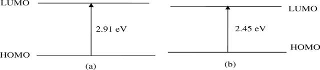
levels (ΔEHOMO-LUMO) using the B3LYP/6-31 G(d,p) method Azaid et al. (2021). Figure 2 shows the HOMO and LUMO energies and the calculated energy differences,
comparing the results of the theoretical methods with the experimental data.
The results obtained by the DFT method were the most reliable, giving a band
gap of 2.71 eV after correction, which is in agreement with the band gap
extrapolated from the experimental absorption spectra (2.45 eV) El Malki et al. (2010). In general, it is
accepted that the theoretical band gaps calculated for isolated chains are
about 0.2 eV higher than the condensed phase values Raftani et al. (2020), and our results are consistent with this expectation.
Thus, the calculated band gaps indicate that the PVK-PEDOT copolymer exhibits
promising electronic properties, The theoretical results are in agreement with
the experimental data.with theoretical results in agreement with the
experimental data.
Equation 1 EL Mhamedi et al. (2022) is used to calculate the electron affinity EA, which
reflects the ability of a material to accept an electron.
![]() (1)
(1)
The energy of the neutral
molecule (E(M)) and the energy of the neutral molecule and the anion (E(M))
were calculated using the B3LYP/6-31G(d,p) level. The HOMO, LUMO, band gap
(Egap) and electron affinity (EA) values of the PVK-PEDOT copolymer are shown
in Table 1.
Figure 1 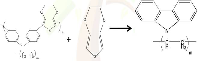
|
Figure 1 PVK–PEDOT Synthesis [20] |
Figure 2
|
Figure 2 The Egap Energies Calculated (a) and Experimental (b) of PVK-PEDOT El Malki et al. (2010) |
The copolymer absorbs light in
the visible (450-800 nm) and ultraviolet (200-450 nm) regions, with a broad
band centered at about 620 nm observed in the visible region. This band is
attributed to a π - π * transition resulting from the presence of
PEDOT moieties in the copolymer and the increase in conjugation length by the
π spacer component of the molecule Nitschke et al. (2021).
Based on these results, the PVK-PEDOT copolymer is considered a promising
material for electronic applications; this applies particularly to the creation
of organic light-emitting diodes.
Table 1
|
Table
1 The
EHOMO, ELUMO, EGAP and EA Energies of the PVK-PEDOT from the DFT Method El
Malki et al (2010) |
|
|||
|
Parameters |
HOMO |
LUMO |
Egap |
EA |
|
Energies
Values(eV) |
-6.59 |
-3.68 |
2.91 |
2.8 |
4. PHYSICAL MODEL
OLEDs use different models to
describe charge transport. The Poole-Frenkel mobility model and the Langevin
bimolecular recombination model are used to explain the polymer transport and
the recombination mechanism, respectively. In addition, the singlet exciton
model is used to calculate the radiative luminescence rate resulting from
Langevin recombination. Each of these models is described both physically and
mathematically. The following equations describe the Poole-Frenkel mobility
model Gill (1972).
![]() (2)
(2)
![]() (3)
(3)
Where μnPF(E) and
μpPF(E) are the Poole-Frenkel mobilities for electrons and holes
respectively, μn0 and μp0 are the zero field mobilities for electrons
and holes respectively, and E is the electric field. DELTAE N.PF MOB and
DELTAEP.PFMOB are the activation energy at zero electric field for electrons
and holes respectively. BETAN.PFMOB is the electron Poole-Frenkel factor, and
BETAP.PFMOB is the hole Poole-Frenkel factor.
Tneff and Tpeff are the
effective temperature for electrons and holes respectively. Due to the strong
dependence on the electric field, the Poole-Frenkel mobility model can cause
convergence problems. To increase the stability of the Poole-Frenkel mobility
model, the following equations are used.
![]() (4)
(4)
![]() (5)
(5)
In OLEDs, electron and hole mobilities are
represented by μn(E) and μp(E), while their limiting mobilities are represented
by μnlim(E) and μplim(E), respectively, calculated from the thermal
velocities. The luminescence rate in the OLED is deduced from the distribution
of singlet excitons. In Atlas software, the singlet exciton continuity
equations are solved simultaneously with the electron and hole drift diffusion
equations Ruhstaller et al. (2001). The bimolecular recombination rate is described by the
Langevin recombination rate, which is expressed by the following analytical
expression.
![]() (6)
(6)
The intrinsic carrier
concentration is represented by ni, and the Langevin recombination rate
coefficient is represented by rL (x, y, t). The latter is defined by the following
expression Blom
et al. (1997).
![]() (7)
(7)
The prefactor of the Langevin bimolecular
recombination model is denoted A. Langevin and depends on the relative
permittivity εr and the absolute permittivity ε0. Its default value
is 1.
5. PRESENTATION
OF THE SIMULATED STRUCTURE
Organic light-emitting diodes
are based on charge carrier injection (the physical phe-nomenon generated by
applying an electric field to the organic material is called injection
electroluminescence). The object of this study is a simulated organic LED,
composed of a PVK-PEDOT layer and a film of organic electroluminescent material
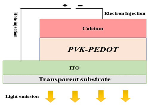
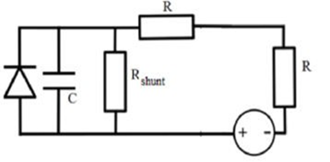
sandwiched between two electrodes. Figure 3 shows the electrical circuit
diagram, while Figure 4 shows the structural diagram of the OLED. ITO (Indium Tin Oxide) material, composed of
indium and tin oxide, is transparent and used as an anode on a glass substrate.
It behaves like an n-type semiconductor, with a wide band gap of 3.5 to 4.3
eV.resulting in high transmission rate (>85%) in the visible and infrared
spectrum. Its superior properties, such as its anti-reflective coating,
electromagnetic field shielding, thermal insulation, and low resistivity, make
it an ideal choice for transparent electrode applications Alam et al. (2000). The calcium (Ca) cathode is produced by repeated
evaporation of calcium layers. The low work function of 2.9 eV improves the
efficiency of electron injection into the organic layers, which facilitates the
creation of organic light-emitting diodes. To realize this electron injection
into the conduction band via the cathode, the diodes use a
sandwich structure. In parallel, holes are injected into the valence band via
the ITO anode. When an electric field is applied, the charge carriers move and
combine to form excitons. These then disappear by radiation emission, which is
the origin of the principle of electroluminescence Janghouri and Mohajerani (2019).
Figure 3
|
Figure 3 OLED Electrical Circuitry |
Figure 4
|
Figure 4 Structure of OLED |
6. RESULTS AND DISCUSSION
6.1. STRUCTURE OF THE SIMULATED LED
The simulation of the organic light emitting diode (OLED)
structure was performed using the ATLAS simulator, which is capable of
providing a comprehensive analysis of organic devices Lysenko et al. (2016). The OLED structure was defined using Atlas syntax, which
allows for the definition of vertical and horizontal lines and their spacing.
Accurate and efficient numerical modeling depends on a well-defined mesh, which
emphasizes its importance. Material parameters such as permittivity, band gap,
electron affinity, effective density of states, hole and electron mobility, as
well as electrode location and doping level in each region were specified for
accurate simulation. The electrical and optical characteristics of the OLED
were then obtained by applying these parameters. The parameters used for the
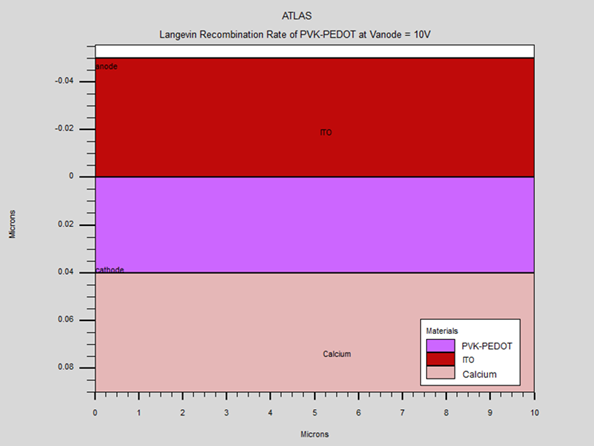
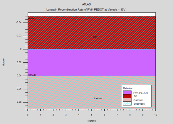
simulation of PVK-PEDOT-based OLEDs are listed in Table 1. This study presents a simulation of an organic LED (OLED) using a
PVK-PEDOT layer. The device configuration consists of an indium tin oxide (ITO)
electrode, the PVK-PEDOT layer, and a calcium (Ca) presented in Figure 5. The results show that the Langevin recombination rate across the
active layer surface is high. Specifically, a significant increase in the
recombination rate is found on the cathode side, while a slight decrease is
observed as the thickness of the PVK-PEDOT layer increases. These results
suggest that the simulated OLED structure exhibits desirable electrical
characteristics.
Table 2
|
Table 2 The different
parameters used for the simulation of PVK-PEDOT for OLEDs |
|
|
Parameters |
Value |
|
Thickness (nm) |
50 |
|
Band gap (eV) |
2.45 |
|
Electron affinity (eV) |
2.8 |
|
Relative Permittivity |
3 |
|
Hole mobility (cm2 /vs) |
10-2 |
|
Electron mobility (cm2 /vs) |
10-4 |
|
Effective density of states in the
conduction band NC300 (cm-3) |
2.1021 |
|
Effective density of states in the valance band (Nv)ND300 (cm-3) |
2.1021 |
Figure 5
|
Figure 5 Simulating OLED Structure using Silvaco Atlas |
Figure 6
|
Figure 6 Effect of Active Layer Thickness on Langevin Recombination Rate in OLEDs |
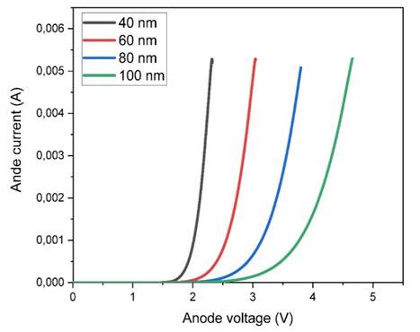
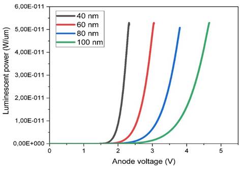
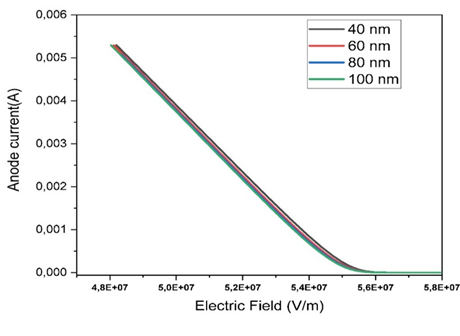
6.2. INFLUENCE OF THE THICKNESS
In this study, we investigate
the effect of varying the active layer thickness (PVK-PEDOT) on the electrical
and optical properties of an organic LED while maintaining a fixed doping
concentration of 1015 cm-3. Figure 6, Figure 7, and Figure 8 show the I-V characteristics, luminescence versus applied voltage, and
current versus electric field, respectively, for active layer thicknesses of
40, 60, 80, and 100 nm. The current-voltage (I-V) characteristic reveals that a
minimum voltage is required to initiate light emission in an OLED. Our
simulation shows that a threshold voltage of 2 volts (VD=2V) is required for a
40 nm active layer. The potential luminescence increases as the anode voltage
increases, and the light intensity decreases as the thickness of the emitting
layer (PVK-PEDOT) increases. This suggests that reducing the thickness of the
active layer leads to improved luminescence and energy efficiency due to
reduced direct charge trapping. Therefore, it can be concluded that a thinner
emitter layer is preferable.
Figure 7
|
Figure 7 Variations of I-V Characteristics of OLEDs as a Function of Emitting Layer Thickness. |
Figure 8
|
Figure 8 Effect of Emitting Layer Thickness on Luminescent Power as aFunction of Anode Voltage |
Figure 9
|
Figure 9 Variation of the Anode Current as a Function of the electric Field for Different Thicknesses of the Active Layer |
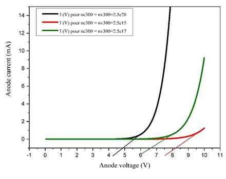
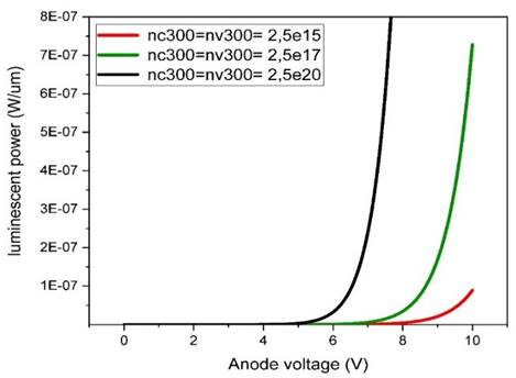
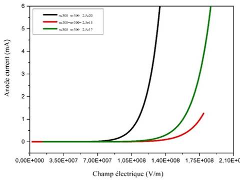
6.3. INFLUENCE OF CHARGE CARRIER DENSITY
The brightness of OLEDs is
directly influenced by the density of the charge carriers, with a higher
density resulting in an increase in the brightness of the device. The
simulation results, presented in Figure 9, Figure 10, and Figure 11. The results present the I-V characteristics, the variation of
luminescence as a function of applied voltage, as well as the evolution of
current as a function of electric field for various charge carrier densities in
the active layer of an OLED with a constant thickness of 40 nm. The results
show that an increase in the anode voltage leads to an increase in the
potential luminescence, while an increase in the thickness of the emitting
layer (PVK-PEDOT) leads to a decrease in the light intensity. Therefore, it can
be concluded that a large value of charge carrier density is beneficial for
OLED performance.
Figure 10
|
Figure 10 Variations of I-V characteristics of OLEDs as a Function of Charge Carrier Density |
Figure 11
|
Figure 11 Effect of Charge Carrier Density on Luminescent Power as a Function of Anode Voltage |
Figure 12
|
Figure 12 Variation of the Anode Current as a Function of The Electric Field for Different Charge Carrier Density |
6.4. INFLUENCE OF TEMPERATURE
In general If temperatures are
too high, this can lead to a reduction in screen brightness and a decrease in
screen life, while temperatures that are too low can affect screen performance
by reducing electron mobility. OLED displays can operate over fairly wide
temperature ranges, typically from -20°C to 70°C. Figure 12 shows the I-V characteristics of OLED for different temperature values
(280K, 300K, 350K, 380K).
Figure 13
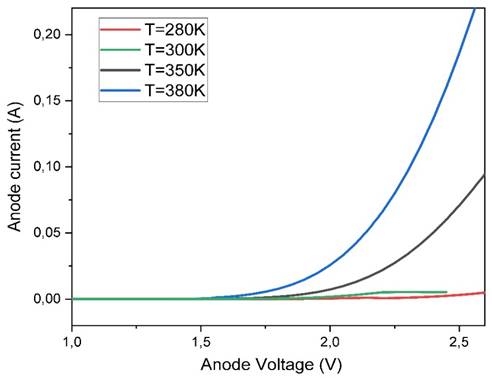
|
Figure 13 Variations of I-V Characteristics of OLEDs as a Function of Temperature |
The threshold voltage, which is
the voltage needed to start emitting light, generally increases with increasing
temperature and increasing temperature can lead to an increase in the current
flowing through the OLED, as it accelerates the mobility of electrons in the
organic materials of the OLED. This can lead to an increase in the brightness
of the OLED display, but it can also accelerate the degradation of the organic
OLED materials and reduce the life of the display. It is therefore important to
adhere to the recommended temperature ranges for optimal OLED display
operation.
7. CONCLUSION
To predict the electrical and optical properties of an OLED with a PVK-PEDOT emitting layer, Silvaco TCAD software was used in this study. The simulation involved solving the differential equations that describe polymer transport and recombination, as well as determining the radiative rate of luminescence resulting from Langevin recombination in the OLED. The TCAD simulation generated I-V characteristics, voltage-dependent luminescence and electric field-dependent current for different thicknesses and charge carrier densities of the emitting layer, as well as I-V characteristics at different temperatures. The results revealed that reducing the thickness improves the device performance, while high charge carrier density and appropriate temperature ranges are crucial for optimal OLED operation. The simulations provide valuable information about the internal physical processes and help optimize the OLED design, reducing the need for time-consuming and costly experiments on real devices.
CONFLICT OF INTERESTS
None.
ACKNOWLEDGMENTS
None.
REFERENCES
Al-Azzawi A.G.S, Aziz S.B, Dannoun
E.M.A, Iraqi A, Nofal M.M, Murad A.R, M. Hussein A (2023). A Mini Review
on the Development of Conjugated Polymers: Steps Towards the Commercialization
of Organic Solar Cells. Polymers, 15, 164,
https://doi.org/10.3390/polym15010164
Alam, M.J., Cameron, D.C. (2000). Optical and Electrical Properties of Transparent Conductive ITO thin films deposited by Sol–Gel Process, Thin Solid Films, 377–378, 0040-6090. https://doi.org/10.1016/S0040-6090(00)01369-9
Azaid, A., Abram, T., Kacimi, R., Sbai, A., lakhlifi ,T., Bouachrine, M. (2021). Organic Materials Based with D– π –A Structure Based on Thiophene and Anthracene for Application in Dye-Sensitized Solar Cells. Materials Today: Proceeding, 45, 7363-7369. https://doi.org/10.1016/j.matpr.2021.01.119
Bakour, A., Saadoune, A., Bouchama, I., Dhiabi, F., Boudour, S., Alam, M.S. (2022). Effect and Optimization of Zno Layer on The Performance of Gainp/Gaas Tandem Solar Cell. Micro and Nanostructures, 168, 2773-0123. https://doi.org/10.1016/j.micrna.2022.207294
Bizzarri, C., Spuling, E., Knoll, D.M., Volz, D., Braese, S. (2018). Sustainable Metal Complexes for Organic Light-Emitting Diodes (OLEDs). Coord. Chem. Rev, 373, 49–82, https://doi.org/10.1016/j.ccr.2017.09.011
Blom,
P.W.M., Jong, M.J.M., and Breedijk, S. (1997). Temperature Dependent
Electron-Hole Recombination in Polymer Light-Emitting Diodes, Applied Physics
Letters, 71, 930-932. https://doi.org/10.1063/1.119692
EL Mhamedi, I., El Karkri, A., and El Malki, Z. (2022).
Simulation of the Performance of Organic Solar Cells Based on
D1-BT-EDOT-BT-D2-A/PCBM Structures, E3S Web Conf., 336,00063. https://doi.org/10.1051/e3sconf/202233600063
El Malki, Z., Hasnaoui, K., Bejjit,
L., Haddad, M., Hamidi, M., Bouachrine, M. (2010). Synthesis,
Characterization and Theoretical Study of New Organic Copolymer Based on PVK
and PEDOT. Journal of Non-Crystalline Solids, 356, 467–473.
https://doi.org/10.1016/j.jnoncrysol.2009.12.017
El karkri, A., El mhamedi, I., and El malki, Z. (2022). Prediction and Simulation of Electrical and Optical Characteristics of an OLED Based on P3BEdotBT3A Organic Material. E3S Web Conf., 336, 00062, https://doi.org/10.1051/e3sconf/202233600062
Gill, W.D. (1972). Drift Mobilities in Amorphous Charge-Transfer Complexes of Trinitrofluorenone and Poly-n-vinylcarbazole, J. Appl. Phys, 55, 12, 5033. https://doi.org/10.1063/1.1661065
Güney, H.Y, Avdan, Z., and Yetkin, H.
(2019). Optimization of Annealing Temperature and the Annealing Effect
on Life Time and Stability of P3HT: PCBM-based Organic Solar Cells. Materials
Research Express, 6, 1-19. https://doi.org/10.1088/2053-1591/aafdee
Heeger, A.J, Macdiarmid, A.G, and Shirakawa, H. (2002). Macromolecules. Am. Chem. Soc, 35,1137–1139, https://doi.org/10.1021/ma0118973
Helfrich, W., and Schneider, W.G. (1965). Recombination Radiation in Anthracene Crystals. Phys. Rev. Lett., 140, 229, https://doi.org/10.1103/PhysRevLett.14.229
Janghouri, M., Mohajerani, E. (2019). Color
optimization of Red OLEDs Via Periodic and Gradient Deposition Rate of
Fuorescent Dopants. Opt. Quant. Electron, 51, 282.
https://doi.org/10.1007/s11082-019-2001-y
Kharchich,
F.Z., Khamlichi, A. (2023). Simulation aided Design of aHigh Efficient
Gasb Based Single-Junction Solar Cell. International Review of Applied Sciences
and Engineering, 2062-0810. https://doi.org/10.1556/1848.2022.00494
Liang, J., Tang, X., Yin, P., Weng, C., Shen, P. (2021). Development of New Nonacyclic Small-Molecule Acceptors Involving Two Benzo[1,2-b:4,5-b] Dithiophene Moieties for Efficient Polymer Solar Cells. Synthetic Metals, 282. https://doi.org/10.1016/j.synthmet.2021.116922
Luo, J., Rong, X.-F., Ye, Y.-Y., Li, W.-Z., Wang, X.-Q., Wang, W. (2022). Research Progress on Triarylmethyl Radical-BasedHigh-Efficiency OLED. Molecules, 27, 1632. https://doi.org/10.3390/molecules27051632
Lysenko, IA.,
Patrashanu, LA., Zykov, DD. (2016). Organic Light
Emitting Diode Simulation Using Silvaco TCAD Tools. International Siberian
Conference on Control and Communications (SIBCON). 2380-6516.
https://doi.org/10.1109/SIBCON.2016.7491782
Nitschke, P., Jarzabek, B., Damaceanu, M.D., Bejan, A.E., Chaber, P., (2021). Spectroscopic and Electrochemical Properties of Thiophene-Phenylene Based Shiff-Bases with Alkoxy Side Groups, Towards Photovoltaic Applications. Spectrochim Act a Mol Biomol Spectrosc, 248. https://doi.org/10.1016/j.saa.2020.119242
Partridge, P.H. (1983).
Electroluminescence from Polyvinylcarbazole lms: 3. Electroluminescent Devices.
Polymer, 24, 748, https://doi.org/10.1016/00323861(83)90012-5
Raftani, M., Abram, T., Azaid, A., Kacimi, R., Bennani,
M.N., and Bouachrine, M. (2021). Theoretical Design of New Organic
Compounds Based on Diketopyrrolopyrrole and Phenyl for Organic Bulk
Heterojunction Solar Cell Applications: DFT and TD-DFT Study. Materials Today:
Proceedings, 45, 7259-7800. https://doi.org/10.1016/j.matpr.2020.12.1228
Raftani, M., Abram, T., Bennani, N., Bouachrine, M.
(2020). Theoretical Study of New Conjugated Compounds with a Low Bandgap
for Bulk Heterojunction Solar Cells: DFT and TD-DFT Study. Results in Chemistry,
100040, 2211-7156. https://doi.org/10.1016/j.rechem.2020.100040
Raj, A., Gupta, M., Suman, D. (2019). Simulation of Multilayer Energy Efficient OLEDs for Flexible Tilayer Energy Efficient. Procedia Computer Science, 152,301–308. https://doi.org/10.1016/j.procs.2019.05.013
Ruhstaller, B., Carter, S.A., Barth, S., Riel, H., Riess, W., Scott, J.C., (2001). Transient and Steady-State Behavior of Space Charges in Multilayer Organic Light-Emitting Diodes, J. Appl. Phys, 89,4575-4586. https://doi.org/10.1063/1.1352027
Semire, B., Oyebamiji, A.K., Odunola, O.A. (2020). Electronic Properties Modulation of D–A–A Via Fluorination of 2-cyano-2-pyran-4-ylidene-acetic Acid Acceptor Unit for Efficient DSSCs: DFT-TDDFT Approach. Scientific African,7, e00287-e00287. https://doi.org/10.1016/j.sciaf.2020.e00287
Singh, R., Narayanan, K.N., Solanki, A. (2012).
Deepak. Improving the Contrast Ratio of OLED Displays: An Analysis of Various
Techniques. Optical Materials, 34,716-723. https://doi.org/10.1016/j.optmat.2011.10.005
Taherinia, D., Fattahi, A. (2022). Inducing High Exo Selectivity in Diels–Alder Reaction by Dimethylborane Substituent: a Dft Study. Sci Rep, 12, 22225. https://doi.org/10.1038/s41598-022-26685-y
Udhiarto, A., Sister, Y., Rini, S., Asvial, M., and Munir, B. (2015). Effect of Hole Transport Layer and Electron Transport Layer on the Performance of a Single Emissive Layer Organic Light Emitting Diode. International Conference on Quality in Research (QiR), Lombok, 137-140. https://doi.org/10.1109/QiR.2015.7374913
Zeng, X., Li, Z., Ren, J., Ge, T., Zang, A., and Sun, Q. (2018). Low bandgap Diketopyrrolopyrrole-Based Polymers with an Asymmetric Unit of Fl Uoridated Phenylene-Thiophene for Efficient Polymer Solar Cells. Synthetic Metals, 240, 30-36. https://doi.org/10.1016/j.synthmet.2018.03.012
 This work is licensed under a: Creative Commons Attribution 4.0 International License
© Granthaalayah 2014-2023. All Rights Reserved.