DESIGN OF TRAIN OPERATION SIMULATION SYSTEM BASED ON
"LAYER " MODEL
Di Qiang 1 1 School of International Energy, Jinan
University, Zhuhai, China
2 Jinan University
Rail Transit Research Institute, Jinan University Zhuhai China
3 Guangdong Province
Electricity and Intelligent Control Engineering Technology Research Center Zhuhai,
China
4 Electric Power
Research Center Jinan University, Zhuhai, China
|
|
||
|
|
|||
|
Received 01 February 2022 Accepted 02 March 2022 Published 25 March 2022 Corresponding Author Yan Dongsong, tyands@qq.com DOI 10.29121/IJOEST.v6.i2.2022.284 Funding: This research
received no specific grant from any funding agency in the public, commercial,
or not-for-profit sectors. Copyright: © 2022 The
Author(s). This is an open access article distributed under the terms of the
Creative Commons Attribution License, which permits unrestricted use, distribution,
and reproduction in any medium, provided the original author and source are
credited.
|
ABSTRACT |
|
|
|
The “layer” model is introduced into train operation
simulation to develop a train operation simulation system (TOSS) ,which can be used for different locomotives, running
parameters and lines. The virtual “layer” model can simulate any long-distance
line on a limited track. The line models of different lines and stations can
be constructed in the TOSS model definition. The system converts the actual
line into the “layer” model, simulates the train operation on the line
through the annular track model, and stores the operation-state parameters
with the “layer” model structure. TOSS can statistically analyze the data
generated through the data analysis subsystem and restore the whole
train-operation process by various animation demonstration. The application
of “layer” model is the core of TOSS, which can realize the train operation
simulation intuitively, and provide decisions basis for route planning,
station docking or train operation scheduling scheme. |
|
||
|
Keywords: Train Operation Simulation, Railway
Simulation, Circular Orbit, Computer Simulation, Layer Model 1. INTRODUCTION
With the further rapid development and expansion of the scale of rail
transit network, the traffic network is becoming more and more complex, and
the line scheduling problem is gradually increasing. The use of field
experiments to solve the train scheduling problem will cause great waste of
time and cost, and lack of security assurance. The construction of train
operation simulation system through computer software is of great
significance for optimizing train operation scheduling scheme Gabor (2001), solving line planning Norbert and Valent (2008), estimating delay and delay propagation Yuan and Hansen (2007).
The design of Railway simulation program is generally divided into two
kinds: one is Macroscopic simulation program based on a group of train
average motion Kettner et al. (2001), Kettner and Sewcyk (2002) second, based on current timetables, detailed
infrastructure data accurately represent microscopic simulation programs of
train movement. In addition, microscopic simulation programs are usually
divided into synchronous microscopic programs Nash and Huerlimann (2004), and Asynchronous microscopic programs. In the
design of this system, synchronous microscopic programs can be used to pass
the ‘layer’ model according to the interval |
|
||
running speed and running time of trains under different operating conditions. The influence of different line states on single train operation is simulated, and the optimal operation scheme of trains is analysed as a reference for operation scheduling management. The results of train simulation can also provide reconstruction scheme for line reconstruction. In addition, the actual road map can be used to analyse the influence between each other when the train is running and simulate the trajectory of the train group to test and determine the operation scheme of the train group.
2. MATERIALS AND METHODS
2.1. TRAIN OPERATION SIMULATION ANALYSIS
Because in the train operation simulation process, when the actual line length is quite large, it is difficult to completely describe all the station information on the line model in the two-dimensional plane. Therefore, this paper proposes a ' layer ' model method, which can convert the actual train line into a model layer and then simulate the train operation. According to the user defined line model, the ' layer ' model virtually converts the line model on the two-dimensional plane to the logical layer model on the three-dimensional plane according to a certain proportion. In other words, the train is not running on the two-dimensional plane, but running on each layer model.
In the actual operation process of the train, according to the operation speed of the train, the train operation process is generally divided into starting, traction acceleration, constant speed, idle running, speed regulation braking and inbound braking. In the process of train operation simulation, due to the setting of specific conditions, multiple conditions can be combined, or a certain condition can be omitted. In this study, the train operation process is divided into three operating conditions: starting acceleration, constant speed, and braking.
2.2. “LAYER” MODEL
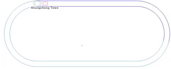
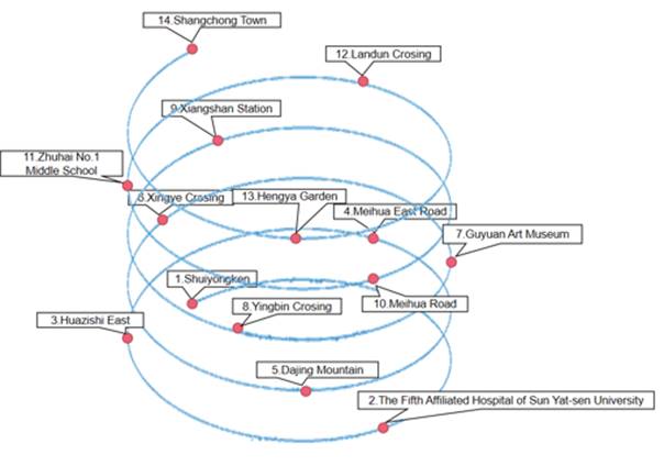
The layer model is a spiral superposition virtual layer based on the annular orbit model. According to the user defined line model, the line model on the two-dimensional plane is virtualized as a spiral ring line on the three-dimensional plane. The spiral annular line is divided into several virtual layer models by equal length. The annular orbit model is shown in Figure 1, and the spiral overlay virtual layer corresponding to a line is shown in Figure 2.
Users complete the definition of the line model by setting the relevant information of the line model, complete the setting of the ring track model by setting the track number, track length and track radius in the track information, and then complete the corresponding relationship between the total track length of the ring track model and the line length of the line model by setting the scale P. For example, when P = 1000, 1cm of the total length of the orbit corresponds to 10m of the actual line. In Figure 1, the orbital length of the annular orbit model is L, and the orbital radius is r, so the total orbital length is 2L + 2πr, in centimetres. The corresponding line model line length is M = (2L + 2πr) × 10, unit is meters.
The division method of layer model is described in detail below. After the line model, track model and scale P are set, the total track length of ring track model corresponds to the line length of line model M. The total length of the line model is divided into the layer model at M intervals, and each layer model corresponds to a circle of the track model, thus the operation of the train on the line model is transformed into the operation of the ring track model corresponding to each layer model. Since the operation of the train on the actual line is coherent and sequential, the order of each layer model should be corresponding to the order of the train running on the line model and the site on each layer model should also be corresponding to the line model.
After the layer model is divided, the image information of the same ring orbit model is saved in the same container. After the current layer model trains return to the starting point of the ring track model, the system automatically obtains images and coordinates from the container that saves image information such as the next layer model station and calls the drawing function to draw on the window interface.
The introduction of the “layer” model can simulate any long-distance line on a limited track. The ' layer ' model has strong applicability, and the flexible selection of scale P can fully display the characteristics of train operation in simulation.
|
|
|
Figure 1 Circular orbit model |
|
|
|
Figure 2 Spiral overlay virtual layer
corresponding to a line |
3. RESULTS AND DISCUSSIONS
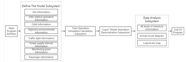
Train operation simulation system is divided into four parts: model definition subsystem, train operation simulation calculation subsystem, ' layer ' model animation demonstration subsystem, data analysis subsystem. When the system is running, first of all, the main program window is entered into the main program, and the model-related information of train simulation operation is set through the model definition subsystem, including station information, train station operation information, track information and passenger information. Then, the time points corresponding to the acceleration, constant speed and braking process are calculated by the train operation simulation calculation subsystem. According to the calculation results, the single train operation simulation animation demonstration is carried out by the “layer” model animation demonstration subsystem. Finally, the data analysis subsystem outputs various statistical information diagrams, actual circuit diagrams and logical station diagrams of trains. The overall structure and data flow of the system are shown in Figure 3.
|
|
|
Figure 3 System structure and data flow
chart |
3.1. MODEL DEFINITION SUBSYSTEM
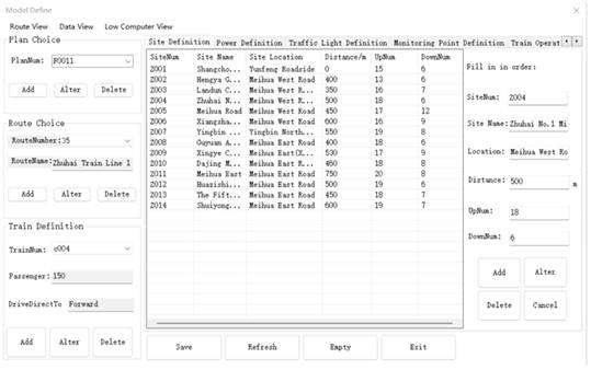
The subsystem can independently set up the model information of train simulation operation and can also select the line model information stored in the software for simulation. Among them, the relevant information of the model includes station information, train station operation information, track information, objective environment information, traffic light information, power supply interval information, monitoring point information and passenger information.
Each definition module can be added, modified, and deleted. After the model definition is completed, the defined model is stored in the database to facilitate subsequent simulation and query analysis. Model definition subsystem interface is shown in Figure 4.
|
|
|
Figure 4 Model definition subsystem
interface |
3.2. TRAIN OPERATION SIMULATION SUBSYSTEM
In the train operation simulation, the train is regarded as a rigid particle, and the train force is concentrated in one point without considering the train length. According to the slope, curve and speed limit of the line, the line is segmented according to the site distribution to ensure that the train has the only additional line resistance and the only speed limit in different segments. The maximum traction force is used in the acceleration process of train operation, the constant speed operation is used in the intermediate process, and the maximum braking force is used in the breaking and entering process.
Train operation is divided into starting acceleration, constant speed, braking three operating conditions to simulate.
1) Start-up acceleration: After the train model starts from the starting point, it is accelerated according to the present speed and start-up acceleration according to different line traffic conditions until the train speed reaches the set value.
2) Constant speed: When the train speed reaches the set value, it enters the constant speed operation state.
3) Braking: Whether the train reaches the time point corresponding to the braking is judged. After reaching the time point, the train model decelerates according to the braking acceleration until the train accurately reaches the station and the train speed is zero.
For the conversion of train operation conditions, the train operation simulation calculation subsystem calculates the time points of the train model condition change by obtaining the present station information, driving speed, and starting acceleration of the model, and then generates the train model operation state table. In the process of train operation simulation, the system sends corresponding control instructions at corresponding time points to control the train running state.
3.3. “LAYER” MODEL ANIMATION DEMO SUBSYSTEM
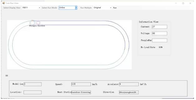
The ' layer ' model animation subsystem is the core of train operation simulation system, which is divided into ' layer ' model module and operation simulation module. The ' layer ' model animation subsystem simulates single train operation in the form of ' layer ' model animation according to the model information set by the model definition subsystem and the calculation results of the train operation simulation subsystem. The ' layer ' model animation subsystem is shown in Figure 5.
|
|
|
Figure 5 The “layer” model animation
demonstration subsystem |
3.3.1. “LAYER” MODEL MODULE
The ' layer ' model module displays the site, power supply interval and red and green lights set by the model definition subsystem by layer, which can avoid the crowded interface of animation demonstration window caused by the simultaneous display of all sites, power supply interval and red and green lights. The introduction of the layer model makes it possible to simulate any long-distance line on a limited track.
The ' layer ' model module constructs the annular orbit model according to the orbit information set in the model definition subsystem. After the current model layer trains return to the starting point of the ring track model, the system automatically obtains images and coordinates from the container that saves image information such as the next layer model station, power supply interval, red and green lights, and calls the drawing function to draw on the window interface.
3.3.2. RUNNING SIMULATION MODULE
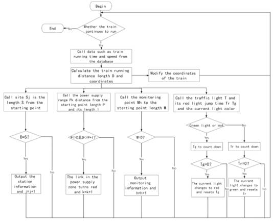
The operation of the train is completed by calculating the coordinates through the trigonometric function and modifying the coordinates of the train model according to the calculation results of the train operation simulation calculation subsystem. The x-axis and y-axis range of the window coordinate system of the track model are both [ − 1, 1]. The length of the track is 2r + L, and the width is 2r. A certain space a is reserved between the two sides of the track and the edge of the window, so the length of the unit track is 2 / (2r + L + 2a), that is, the scale, and the track coordinate is calculated according to the scale. The distance length of train operation can be obtained by calling the calculation results of train operation simulation calculation subsystem in the database in real time during train operation.
When the train is running, it is necessary to judge whether the train reaches the station. If the train is a tram, it is also necessary to judge whether it reaches the power supply interval, and the intersection traffic lights. Run the simulation module process as shown in Figure 6.
|
|
|
Figure 6 Flow chart of running simulation
module |
3.4. DATA ANALYSIS SUBSYSTEM
The data analysis subsystem analyses the generated data to provide the basis for decision-making, and can output the simulation results in various forms, including various statistical information diagrams of trains, actual circuit diagrams, and logical station diagrams.
1) Statistical analysis results of trains: Statistical analysis results of different operation schemes, such as train speed monitoring map, time, passenger, station information map, etc.
2) The actual road map: By calling Baidu map, the operation of the train on the actual line is displayed. At the same time, the train group operation simulation can be carried out to test and determine the operation scheme of the train group.
3) Logic station diagram: display logic station diagram, dynamic demonstration of train location information and train operation data information.
4. CONCLUSIONS AND RECOMMENDATIONS
Train operation simulation plays an important role in basic train operation planning, train operation line planning and station parking. In this paper, the train operation simulation system based on ' layer ' model is designed to solve the problem of train operation simulation of long distance and arbitrary lines. It can simulate the influence of different line states on train operation, analyse the optimal operation scheme of trains and serve as a reference for operation management. In addition, the operation scheme of train groups can be tested and determined. The system has strong applicability. It is not only suitable for metro, tram and other locomotives in urban rail transit, but also for high-speed railway train operation control system. It can be applied to the simulation of different lines and different locomotive types and has certain research value.
ACKNOWLEDGEMENTS
Funding: This research was supported by the National College
Students' Innovation and Entrepreneurship Project, the Train Simulation
Operation Monitoring System Based on Digital Twin (202110559067).
Copyright: © 2022 The Author(s). This is an open access article distributed under the terms of the Creative Commons Attribution License, which permits unrestricted use, distribution, and reproduction in any medium, provided the original author and source are credited.
REFERENCES
A. Norbert, K. Valent. (2008) Optimization of Railway Terminal Design and Operations Using Villon Generic Simulation Model, Department of Transportation Networks, University of Zˇ ilina, Univerzitna', Slovak Republic, October. Retrieved from https://www.tandfonline.com/doi/abs/10.3846/1648-4142.2008.23.335-340
J. Yuan, I.A. Hansen, (2007) Dealing with stochastic dependence in the modeling of train delays and delay propagation, Transport. Res. 202-217. Retrieved from https://doi.org/10.1061/40932(246)641
M. Kettner, B. Sewcyk, (2002) A model for transportation planning and railway network evaluation, in : Proceedings Of The 9th World Congress On Intelligent Transport Systems, Chicago, USA, October, pp. 1417. Retrieved from https://trid.trb.org/view/661976
M. Kettner, R. Prinz, B. Sewcyk, (2001) NEMO - NetzEvaluationsmodell Bei Den OBB, Eisenbahntechnische Rundschau (ETR) 3 117-121.
Nash A, Huerlimann D. (2004) Railroad simulation using OpenTrack. WIT Transactions on The Built Environment, 74 Retrieved from https://www.witpress.com/elibrary/wit-transactions-on-the-built-environment/74/12035
S. Gabor, (2001) Railway Simulation with the CASSANDRA Simulation System, Budapest University of Technology and Economics, Budapest, Hungary, Retrieved from https://hrcak.srce.hr/44814
 This work is licensed under a: Creative Commons Attribution 4.0 International License
© Granthaalayah 2014-2022. All Rights Reserved.