ESTIMATION OF NUCLEAR FUSION REQUIREMENTS IN BUBBLES DURING ULTRA-HIGH-PRESSURE, ULTRA-HIGH-TEMPERATURE CAVITATION PROMOTED BY MAGNETIC FIELDToshihiko Yoshimura 1 1 Department of Mechanical Engineering, Sanyo-Onoda City
University, 1-1-1 Daigaku-Dori, Sanyo-Onoda, Yamaguchi 756-0884 Japan.
2 Department
of Mechanical Systems Engineering, Tokyo Metropolitan University 1-1 Minami-Osawa,
Hachioji, Tokyo 192-0397, Japan. 3 Graduate School of
Advanced Science and Engineering, Hiroshima University 1-4-1 Kagamiyama,
Higashi-Hiroshima, Hiroshima 739-8527, Japan. |
|
||
|
|
|||
|
Received 1 September 2021 Accepted 15 September2021 Published 31 December 2021 Corresponding Author Toshihiko
Yoshimura, yoshumura-t@rs.socu.ac.jp DOI 10.29121/IJOEST.v5. i6.2021.257 Funding:
This
research received no specific grant from any funding agency in the public,
commercial, or not-for-profit sectors. Copyright:
© 2021
The Author(s). This is an open access article distributed under the terms of
the Creative Commons Attribution License, which permits unrestricted use, distribution,
and reproduction in any medium, provided the original author and source are
credited.
|
ABSTRACT |
|
|
|
In the
present work, a strong magnetic field was applied near the outlet of the
water jet nozzle to promote the generation of multifunction cavitation
bubbles. Because these bubbles contained charged species, the bubbles
experienced a Lorentz force due to the magnetic field and collided with
greater force. As such, the internal bubble pressure exceeded the threshold
value required for fusion to occur. The expansion of these charged bubbles in
response to ultrasonic irradiation affected adjacent charged bubbles so that
the energy density of the atoms in the bubbles was greater than the fusion
threshold. The results of this work strongly suggest that the formation of
bubbles via the UTPC process in conjunction with a strong magnetic field may
result in bubble fusion. |
|
||
|
Keywords: Multifunction Cavitation, High-Pressure High-Temperature Cavitation,
Bubble Fusion, Magnetic Field, Charged Cavitation Bubbles, Lorentz Force. 1. INTRODUCTION Fusion reactions have
been used to raise the temperature of plasmas, and some aspects of this
process, such as the external energy required to raise the temperature of the
plasma, the state of the plasma at critical points, and the effects of heavy
hydrogen, have been investigated. In order for the deuterium-tritium (D–T)
fusion reaction to occur, the tritium nucleus must experience a pressure of
1.0 × 10¹¹ atm (1 × 10¹⁰ MPa) and a temperature of 1.0
× 108 °C. Taleyarkhan 's group previously reported deuterium
fusion in a beaker filled with ultrasonically-irradiated organic solvents at
high temperature and pressure Taleyarkhan et al.
(2002), Seife (2002). In this prior
work, ultrasonic waves were applied to acetone containing deuterium to
generate cavitation, and neutrons that were expelled in conjunction with the
rupture of small bubbles in the fluid were captured. Unfortunately, this work
was never satisfactorily reproduced. Our own group previously
developed high-temperature, high-pressure cavitation processes referred to as
either multifunction cavitation (MFC) (Yoshimura et al. 2019, International
PCT published patent WO2016136656A1, US registered patent, Inventor:
Toshihiko Yoshimura, Assignee: Sanyo-Onoda City Public University, US Patent No.
10,590,966 B2, |
|
||
Date of Patent: Mar. 17, 2020) Yoshimura
et al. (2018a) or ultra-high-temperature and
pressure cavitation (UTPC) Yoshimura
et al. (2018b). It should be noted that both MFC and
UTPC operate on the same principles but differ in the dimensions of the
equipment used. These techniques are able to generate compressive residual
stress on material surfaces, improve corrosion resistance and oxidation
resistance, and form tough layers that resist cracking. Using these methods,
our group has modified the surfaces of low alloy steels, aluminum alloys Yoshimura
et al. (2021a), magnesium alloys Ijiri et
al. (2021), Ni-based superalloys and titanium
dioxide particles Yoshimura
et al. (2018a).
Previous
work has demonstrated that MFC processing in which water jet cavitation (WJC)
is combined with ultrasonication in deuterated acetone could potentially result
in bubble fusion Yoshimura
et al. (2018c). However, it is unlikely that the
pressures that are generated during bubble shrinkage will exceed the threshold
pressure required for bubble fusion or that the energy density of the atoms in
the bubbles during bubble shrinkage will exceed the fusion threshold. In
addition, because deuterated acetone is expensive, prior work showed that it is
necessary to reduce the size of the equipment.
In the
present study, reduced size UTPC equipment was prototyped. UTPC processing was
subsequently performed by applying a strong magnetic field during cavitation,
which was found to increase the pressure associated with bubble shrinkage. The
possibility that this process would cause the bubble pressure to exceed the
threshold value necessary for fusion was studied. We also investigated the
likelihood that the energy density of the atoms in the bubble during bubble
shrinkage would exceed the value necessary for fusion.
2. EXPERIMENTAL
2.1 PROTOTYPE REDUCED SIZE UTPC EQUIPMENT
WJC
has a peening effect that imparts compressive residual stress to the surface of
a material due to the very high pressures generated during the collapse of
microjets near the surface Kling
(1970), Summers
(1987). In the case that ultrasonic waves
are applied to WJC bubbles, isothermal expansion occurs when the pressure
around the bubbles exceeds Blake threshold Atchley
1989. Therefore, the bubbles are able to
overcome the effects of surface tension (that is, Laplace stress) and expand
significantly in the case that A ≥ ABlake, where ABlake
is the Blake threshold Atchley
1989. During this process, the isothermal
expansion and adiabatic compression of bubbles produce so-called hot spots Gompf et
al. (1997) generated in the microjets at which
chemical reactions can occur, resulting in mechanical and electrochemical
effects. This series of events represent the basic principle of MFC. The
accompanying bubble temperatures can be estimated by sonoluminescence (SL).
This is a phenomenon in which pulsating bubbles, which can concentrate diffuse
sound energy by a factor of 12 orders of magnitude Barber
and Putterman (1991), produce very short flashes of
ultraviolet light Barber
et al. (1997), Putterman
and Weninger (2000).
Various
techniques have been developed to raise the temperature and pressure of
cavitation bubbles during the MFC process. Although these trials have used
water as the liquid medium, the basic results can also be applied to other
liquids such as deuterated acetone. The pump discharge pressure is an important
factor in the production of high-pressure microjets, and a pressure of 35 MPa
or higher is required to obtain the high collapse pressure of the microjet. The
number of cavitation bubbles depends on the flow rate of the liquid, while the
diameter of the liquid jet nozzle affects the size of the cavitation bubbles as
well as the flow rate and speed of the liquid jet Yoshimura
et al. (2021b). The diameter of the nozzle used to
perform surface modification in a UTPC system is 0.8 mm. However, in order to
achieve a discharge pressure of 35 MPa with this nozzle diameter, a flow rate
of 7 L/min is required, which necessitates a large reaction vessel. This, in
turn, leads to economic challenges related to the use of deuterated acetone.
For these reasons, a prototype bubble fusion apparatus was designed to provide
a more compact MFC process Yoshimura
et al. (2021c) based on a 0.1 mm nozzle with a
flow rate of 150 mL/min. This device was originally developed to permit
nano-level processing of titanium oxide, which is a photocatalytic material, in
conjunction with SL measurements during MFC. This work reduced the overall size
of the equipment. As shown in Figure 1, a swirl flow nozzle (SFN) [4] was
mounted on the liquid jet nozzle to increase the size of the liquid jet
cavitation generated from the 0.1 mm nozzle.
Table 1 summarizes the specifications for
the prototype small-scale bubble fusion equipment. Figure 1 presents a diagram of the equipment
designed by 3D-CAD, while Figure 2(a)
provides a photographic image of the exterior of the apparatus. During
operation of this equipment, the reaction vessel was evacuated in order to
degas the deuterated acetone, using a rotary pump. The apparatus used in the
experiments with a 0.1 mm nozzle also included a high-pressure pump (L. TEX
Corp., LTEX8731E) having a maximum pressure of 40 MPa and a maximum discharge
rate of 200 mL/min together with 50 W ultrasonic transducers (Honda Electronics
Corp., WSC28TH, HEC-45282) each having a frequency of 28 kHz and an output
power of 40 W. Because the UTPC device was equipped with a swiveling water jet
nozzle, the bubbles underwent a greater expansion so that the UTPC process was
realized Yoshimura
et al. (2018b). Acetone was supplied from a holding
tank to the high-pressure pump and a 40 MPa acetone jet was ejected from the WJ
nozzle. Figure 2(c)
and 2(d) show photographic images of the MFC
process using acetone. During operation of this equipment, bubbles were
generated in the acetone and underwent coalescing growth near the center of the
nozzle with occasional coalescence and growth at more distant locations. In
future work, our group intends to examine the mechanism by which these bubbles
in acetone form aggregated chain structures that are not observed in water
|
Table 1 Specifications of prototype small-scale bubble fusion equipment |
|
|
|
|
|
Figure 1 Schematic diagram of the
prototype small-scale bubble fusion equipment |
|
|
|
Figure 2 Photographic images of (a) the prototype
small bubble fusion equipment and (b, c) the resulting MFC bubbles |
2.2 ACTIVATION OF THE MFC BUBBLES BY A STRONG MAGNETIC FIELD
A
basic experiment concerning the activation of MFC bubbles was carried out by
applying a strong magnetic field at atmospheric pressure while using the
reduced size MFC equipment equipped with a 0.1 mm nozzle. As noted, this
apparatus was previously developed for nano-level processing of titanium oxide
in conjunction with SL measurements. The field was applied by placing two
strong neodymium permanent magnets (Sangyo Supply Co., Ltd., N40) at the base
of the device, facing the water jet nozzle. These magnets had dimensions of 20
mm × 7 mm × 10 mm (± 0.1 mm) and were magnetized along the 10 mm thickness
direction. After applying these magnets, jets of pure water showed an increase
in the number of bubbles, demonstrating that the WJC process was activated in the
presence of a strong magnetic field.
During
the MFC process, high-temperature, high-pressure bubbles were generated
containing H+, OH- and electrons due to the thermal decomposition of water
vapor, and these charged species were affected by the Coulomb force imparted by
the magnetic field. Throughout the cavitation process induced by the WJ nozzle,
bubbles were repeatedly generated, grew and collapsed, and the collapse of
these cavitation bubbles produced many new bubbles to form a cavitation cloud.
The Coulomb force imparted by the magnetic field likely promoted collisions
between bubbles during bubble collapse, leading to an increase in the number of
bubbles that were generated and further development of the cavitation cloud. To
date, the activation of liquid cavitation bubbles in this manner has not been
reported, although there has been research regarding SL in the presence of high
magnetic fields Young et
al. (1996). During trials in water, changes in
the magnetic field at a constant sound pressure have been found to cause the SL
signal to disappear when a threshold magnetic field value is exceeded. It has
also been shown that varying the sound pressure with a fixed magnetic field
dramatically increases the upper and lower limits of the pressure around the
bubble that define the range over which SL will appear Young et
al. (1996).
Placing
two neodymium magnets at the base of the water tank against the nozzle outlet
(as shown in Figure 2) was found to generate a magnetic
flux density at the nozzle outlet of 0.23 mT. During the actual trials, four
magnets were affixed to the vertical wall surface of the nozzle part of the
apparatus while another four magnets were applied to both sides of the water
vessel wall at the position at which the cavitation cloud was formed. A further
four magnets were placed on the vertical wall surface where the ultrasonic
transducer was located, for a total of 14 magnets. It should be noted here that
the S pole N pole magnetic circuit was constructed so that the polarities of
the opposing surfaces were different, and so the magnetic flux at the nozzle
outlet was increased to 1.2 mT. It is also important to note that increasing
the number of magnets would be expected to generate a higher magnetic field of
100 mT or more at the nozzle outlet.
Employing
an odd number of ultrasonic transducers that produced ultrasonic waves from the
periphery to the center of the liquid jet in conjunction with the strong
magnetic field from the nozzle outlet to the cavitation cloud generated
cavitation bubbles having a high energy density. It was anticipated that this
phenomenon would occur in deuterated acetone as well as in water so that bubble
fusion could be realized.
3. BUBBLE FUSION THEORY
3.1 BUBBLE PRESSURE AND TEMPERATURE
The Keller-Miksis formulation Keller
and Miksis (1980), Gaitan
et al. (1992)is an equation describing the large,
radial oscillations of a bubble trapped in a sound field. When the frequency of
the sound field approaches the natural frequency of the bubble, large amplitude
oscillations will occur. This equation takes into account viscosity, surface
tension, incident sound waves and acoustic radiation coming from the bubble.
The latter factor was not previously incorporated in Lauterborn's calculations
based on the equation that Plesset et al. modified from Rayleigh's original
analysis Rayleigh
(1917), Plesset
(1949) of large oscillating bubbles Keller
and Miksis (1980). Keller and Miksis obtained the
equations Gaitan
et al. (1992):
![]() (1)
(1)
and
![]() (2)
(2)
Where
R ̇ is the velocity of the bubble wall, R ̈ is the acceleration of
the bubble wall, s is
the surface tension, µ is the viscosity coefficient for acetone, p0
is atmospheric pressure, pA(t+R/c) is the supersonic sound pressure as a function
of time, t, c is the velocity of sound, p∞ is the atmospheric pressure,
and pB(R,t) is the liquid pressure at the
bubble interface.
Because the prototype small-scale UTPC
equipment used a 0.1 mm nozzle, the radius of the water jet cavitation bubbles
was smaller than that obtained using a larger 0.8 mm nozzle, which was
approximately 100 μm Yoshimura
et al. (2021b). However, because the UTPC apparatus
incorporated a swivel nozzle attached to the water jet nozzle, the bubbles were
enlarged compared with those obtained during MFC without a swivel nozzle Yoshimura
et al. (2021c). Using the Keller-Miksis formulation,
the changes in bubble radius and internal pressure and temperature in acetone
were calculated for an initial bubble size of 10 μm, a sound pressure of 1
atm and a bubble contraction to 0.1 μm. As previously reported Yoshimura
et al. (2018c), the shrinkage pressure associated
with MFC equipped with a large 0.8 mm nozzle was 7.51 × 10⁷ MPa,
while that during UTPC using a small 0.1 mm nozzle was determined to be 1.10 ×
105 MPa. In addition, the temperature at the time of shrinkage was
1.68 × 10¹² K for the large-scale equipment [Yoshimura et al.
(2018c)] and 3.07 × 10¹² K for the smaller apparatus, due to the higher
expansion coefficient of the bubbles (3.75 = 37.5/10). In previous work Zoghi-Foumani and Sadighi-Bonabi (2014) with an initial bubble radius of
5.10 μm, the bubble internal temperatures were determined to be in the
range of 106 K < T < 107 K. In reality, as the
temperature inside the bubbles increases, the upper limit is determined by
thermal decomposition of the deuterated acetone vapor, chemical reactions and
thermal conductivity. The present calculations indicated that the temperature
inside bubbles exceeded 1.0 × 10⁸ K, which is the value required for
bubble fusion. However, both the large and small-scale equipment generated
internal bubble pressures much smaller than the value of 1.0 × 10¹⁰ MPa
required for fusion. To address this problem, it was determined that an energy
other than the WJ and ultrasonic energy sources was required.
|
|
|
Figure 3 The (a) acoustic pressure, (b)
bubble radius, (c) bubble internal pressure and (d) bubble internal
temperature in acetone as functions of time for various processes |
3.2 COLLISIONS BETWEEN BUBBLES DUE TO LORENTZ FORCE
The
force between two charges q1 and q2 associated with charged bubbles is:
![]() (3)
(3)
where
e is the elementary charge (1.602 × 10⁻¹⁹ C), and ε0 is the
permittivity of a vacuum (8.854 × 10⁻¹² C/Vm). These two charges can
be calculated as:
![]() (4)
(4)
and
![]() (5)
(5)
where
Mq1 and Mq2 are the moles of ions in the two charged
bubbles.
The
Lorentz force can then be approximated as:
![]() (6)
(6)
Where
B is the magnetic flux density (T), and v is the flow velocity of the charged
bubble. The cross product of these terms is:
![]() (7)
(7)
The
pressure inside a bubble having a radius of 10 μm (which is the initial
radius calculated using the Keller-Miksis formulation) that collides with a
charged bubble in conjunction with shrinkage to 0.1 μm was calculated.
Based on a nozzle diameter of 0.1 mm and flow rate of 160 mL/min, the flow
velocity at the nozzle outlet was determined to be 340 m/s if the outlet loss
was ignored. Because the flow velocity decreased on leaving the nozzle
discharge part, the Lorentz force was calculated using equation (6) with the
flow velocity near the outlet set to 100 m/s. Although the number of charged
ions obtained from a WJC process is less than that generated during MFC, it was
assumed that the water vapour was thermally decomposed in the WJC bubbles to
generate ions.
When
the two neodymium magnets shown in Figure 1were placed in the lower part of the
apparatus facing the nozzle, the magnetic force lines from the north to south
poles of the magnets crossed the liquid injection direction near the nozzle
outlet. The cross product (that is, the outer product) of the velocity, v, of
the charged particles and the magnetic field, B, equalled the Lorentz force, F,
based on Fleming's left-hand rule. The Lorentz force acted perpendicular to the
direction in which the charged cavitation bubbles flowed such that the bubbles
collided.
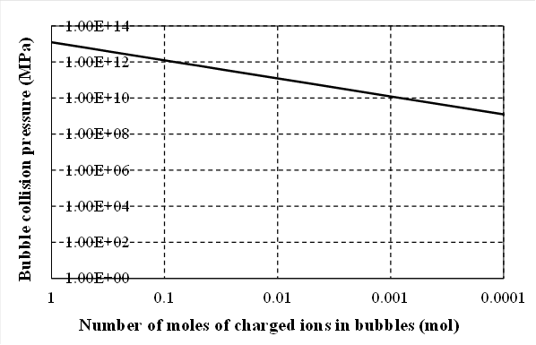
It was assumed that the magnetic
flux density was 100 mT near the WJ nozzle of the small-scale UTPC equipment
and that charged bubbles would collide with uncharged bubbles due to the
Lorentz force of the magnetic field during shrinkage. The relationship between
the number of moles of charged ions in a charged bubble and the pressure of the
bubble collision is shown in Figure 4. In the case that 0.001 moles of
charged ions were present, the collision pressure would be expected to exceed
the 1.0 × 10¹⁰ MPa required for bubble fusion. Further increasing
the magnetic field would be expected to lower the number of moles of ions
required to achieve the threshold pressure.
|
|
|
Figure 4 Bubble collision pressure
during shrinkage as a function of the number of moles of charged ions in a
bubble (flow velocity: 100 m/s) |
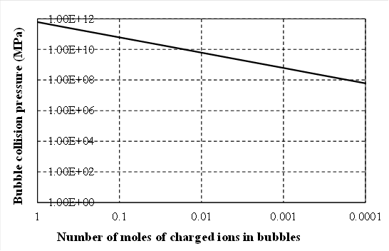
The
flow velocity decreases at the position at which the cavitation cloud grows.
The threshold pressure at which the bubbles expand isothermally is the Blake
threshold Atchley1989., and this value increases along
with the cavitation flow velocity. Therefore, in the case that the bubble flow
velocity decreases, the Blake threshold is also reduced such that a large
number of MFC bubbles are generated and the bubble temperature rises.
Consequently, the number of ions resulting from thermal decomposition in the
bubbles increases. Figure 5 plots the relationship between the
number of moles of charged ions in the bubbles and the bubble collision
pressure due to the Lorentz force for a bubble flow velocity of 5.0 m/s at the
Blake threshold pressure. In excess of 0.017 moles of charged ions were
required in a charged bubble to exceed the threshold pressure of 1.0 × 10¹⁰
MPa. The formation of these ions was promoted by repeated isothermal expansion
and adiabatic compression of bubbles during the UTPC process. Therefore, the
reduction in collision pressure did not occur. Increasing the magnetic flux
density above 100 mT caused the pressure to exceed the threshold value for
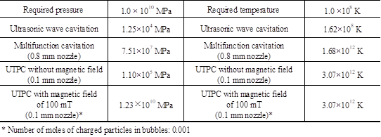
bubble fusion even with a small number of ions in the bubble (Table 2). It should be noted that, in the
case that a collision plate (a specimen for the surface modification of a
material) is installed in the cavitation cloud, the flow direction changes when
the cavitation cloud collides with the plate, which complicates the direction
in which the Lorentz force acts
|
|
|
Figure 5 Bubble collision pressure
during shrinkage as a function of the number of moles of ions in the bubbles
(flow velocity: 5.0 m/s) |
|
Table 2 Maximum internal pressures and temperatures of bubbles during UC
and MFC in an acetone reaction furnace and required pressure and temperature
values for the D-T fusion reaction |
|
|
Footnote:
D + T → 4He + n (14 MeV)
3.3 BUBBLE ENERGY DENSITY
The
bubble spacing resulting from expansion, L, can be calculated as
![]() (8)
(8)
Where
Rmax/R0 is the bubble expansion rate and R0 is the initial bubble radius. The
bubble movement due to expansion, Δr, can be calculated as:
![]() (9)
(9)
Were r
is the initial distance between q1 and q2.
The
amount of work required to move charge q2 toward charge q1 by Δr is
![]() (10)
(10)
The
increase in the energy density within each bubble, ΔE, is:
![]() (11)
(11)
The
increase in energy density per atom, ΔE/atom can be calculated as:
![]() (12)
(12)
Where
NA is Avogadro’s number (mol-1; 6.022 × 10²³).
In the
case that a charge q2 is moved by an electric field E(r) we have the
energy density Ed:
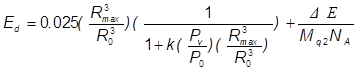 (13)
(13)
Which
can also be written as:
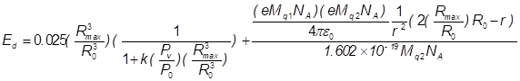 (14)
(14)
Where
k is the fraction of vapour escaping condensation and Pv is the vapour pressure
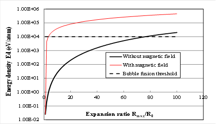
of the host liquid. A plot of Ed versus Rmax/Ro is presented in Figure 6. The fusion energy threshold is
known to be 104 eV per atom or molecule Arakeri
(2003) and k was assigned a value of 0.025
based on the results of Storey and Szeri Storey
and Szeri (2000). Using this value together with
Pv/Po = 10-5 (which is typical of fluids such as ethylene glycol; Po
= 1 bar), it appears that the required energy density, Ed Arakeri
(2003), can be obtained with an expansion
ratio of approximately 75 Yoshimura
et al. (2018c). Thus, assuming that the k value of
acetone is relatively low, it should be possible to obtain the required energy
density
If the
proportion of steam escaping condensation in heavy acetone can be estimated,
the enlargement ratio for bubbles exceeding the threshold can be obtained. The
temperature at the time of bubble shrinkage calculated from equations (1) and
(2), as shown in Figure 3, was assumed to be the number of
vapor moles of the initial bubbles in the standard state. This quantity of
moles also changed with the bubble volume. This is based on the assumption that
the vapor in the bubble flows out of the bubble wall during expansion, and also
flows out of the bubble wall in a manner similar to breathing during shrinkage.
However, although the energy in the bubble increases, primarily due to changes
in pressure and volume, if the amount of steam remaining in the bubble is too
large, the temperature cannot be expected to rise Yoshimura
et al. (2018c). Assuming that the number of moles
in the bubble remains constant, the temperature during bubble contraction will
not increase. In addition, the temperature will rise as the proportion of
residual acetone that escapes evaporation, pyrolysis and condensation decreases
Yoshimura
et al. (2018c). In the case of acetone, Pv/Po =
0.242 and k = 1 × 10⁻⁶. As shown in Figure 6, without the magnetic
field, an Rmax/Ro greater than 77 allows Ed to exceed the threshold of 1 × 10⁴
eV/atom. Thus, in order to obtain a high value of Ed and realize bubble fusion,
it is necessary to increase Rmax/Ro and to decrease k. Increasing the expansion
rate of the heavy acetone bubbles thus necessitates further increases in the
sound pressure.
The
data in Figure 6 also show the relationship between
the expansion coefficient and the energy density when the increase in energy
density due to the expansion of UTPC bubbles in a strong magnetic field was
incorporated based on using equation (14). Here, it is assumed that a bubble
having a charge q1 has an initial radius of 10 μm and is in
contact with a bubble having a charge q2, which has the same initial
radius. Upon expanding in response to ultrasonic waves, the first bubble moves
the second bubble and thus performs work. As an example, if both bubbles have
an expansion factor of 1.5 with an inter-bubble distance of 30 μm, the
movement amount is 10 μm to give a new inter-bubble distance of 20
μm. In the case that the expansion coefficient for the initial 10 μm
bubble shown in Figure 3is 3.75, Ed becomes 1.19 × 10⁴
eV/atom, which exceeds the threshold value of 1.0 × 10⁴ eV/atom.
These calculations suggest that it should be possible to realize bubble fusion
based on a realistic ultrasonic sound pressure.
|
|
|
Figure 6 Bubble energy density versus
expansion ratio for k = 1 × 10⁻⁶ and Pv/Po = 0.242. The dashed
line shows the fusion threshold of 104 eV per atom or molecule |
4. CONCLUSION
In
order to carry out bubble fusion experimentally, the present work employed a
prototype small-scale MFC apparatus to perform UTPC in association with a
strong magnetic field. The following conclusions were obtained.
1)
When
the WJC generated using a 0.1 mm nozzle via the small-scale equipment was
combined with ultrasonication, the pressures and temperatures inside the
bubbles during bubble shrinkage could be estimated using the Keller-Miksis
equation.
2)
A
strong magnetic field was applied near the outlet of the liquid jet nozzle to
promote the generation of MFC bubbles. Because these bubbles contained charged
species, they experienced a Lorentz force due to the magnetic field and
underwent stronger collisions. The resulting bubble pressures exceeded the threshold
value necessary for bubble fusion.
3)
The
expansion of charged bubbles in response to changes in the sound pressure due
to ultrasonic irradiation caused these bubbles to perform work on adjacent
charged bubbles. As a consequence, the energy density of the atoms in the
bubbles exceeded the threshold required for bubble fusion.
4)
The
results of this work strongly suggest that ultra-high temperature and pressure
cavitation within a strong magnetic field may cause bubble fusion.
Acknowledgement
This research was supported in part by a JSPS KAKENHI Grant-in-Aid for Scientific Research (C) (grant no. 19K04110).
REFERENCES
Arakeri H V. (2003) Sonoluminescence and bubble fusion. Current Science ; 85(7) : 911-916. Retrieved from https://www.jstor.org/stable/24108772
Atchley A. (1989) The Blake threshold of cavitation nucleus having a radius-dependent surface tension. J. Acoust. Soc. Am. ; 85(1) : 152-157. Retrieved from https://doi.org/10.1121/1.397724
Barber B P, Hiller R A, Ritva L S, Putterman J K, Weninger R. (1997) Defining the unknowns of sonoluminescence. Phys Rep. ; 281 : 65-143. Retrieved from https://doi.org/10.1016/S0370-1573(96)00050-6
Barber B P, Putterman S. (1991) Observation of synchronous picosecond sonoluminescence. Nature ; 352 : 318-320. Retrieved from https://doi.org/10.1038/352318a0
Gaitan D F, Crum Lawrence A, Church C C, Roy R A. (1992) Sonoluminescence and bubble dynamics for a single, stable, cavitation bubble. Journal of the Acoustical Society of America ; 91(6) : 3166-3183. Retrieved from https://doi.org/10.1121/1.402855
Gompf B, Gunther R, Nick G, Pecha R, Eisenmenger W. (1997) Resolving sonoluminescence pulse width with time-correlated single photon counting. Phys Rev Lett. ; 79 : 1405-1408. Retrieved from https://doi.org/10.1103/PhysRevLett.79.1405
Ijiri M, Yamaguchi K, Kikuchi S, Kato F, Kunieda Y, Sakurai H, Ogi T, Yoshimura T. (2021) Formation of a phosphoric acid compound film on an AZ31 magnesium alloy surface using cavitation bubbles. Surface and Interfaces ; 25 : 101194-1-11. Retrieved from https://doi.org/10.1016/j.surfin.2021.101194
Keller J B, Miksis M. (1980) Bubble oscillations of large amplitude. Journal of the Acoustical Society of America ; 68 (2) : 628-633. Retrieved from https://doi.org/10.1121/1.384720
Kling CL. (1970) A High speed photographic study of cavitation bubble collapse. University Michigan Report No. 03371-2-T : 08466-7-T. Retrieved fromhttps://apps.dtic.mil/sti/citations/AD0705375
Plesset M W. (1949) The dynamics of cavitation bubbles. Journal of Applied Mechanics: 16277-16282. Retrieved from https://doi.org/10.1115/1.4009975
Putterman S, Weninger K. (2000) Sonoluminescence : How bubbles turn sound into light. Ann Rev Fluid Mech. ; 32 : 445-476. Retrieved from https://doi.org/10.1146/annurev.fluid.32.1.445
Rayleigh L. (1917) On the pressure developed in a liquid during the collapse of a spherical cavity. Philosophical Magazine ; 34(200) : 94-98. Retrieved from https://doi.org/10.1080/14786440808635681
Seife C. (2002) Bubble Fusion Paper Generates A Tempest in a Beaker. Science ; 295 :1808-1809. Retrieved from https://doi.org/10.1126/science.295.5561.1808
Storey B D, Szeri A J. (2000) Water vapor sonoluminescence and sonochemistry. Proc. R. Soc. London Ser. A. ; 456 : 1685-1709. Retrieved from https://doi.org/10.1098/rspa.2000.0582
Summers D. (1987) Consideration in the design of a waterjet device for reclamation of missile casings. Proc of the 4th U.S. Water Jet Conference, The University of California, Berkeley : 82-89. Retrieved from https://scholarsmine.mst.edu/min_nuceng_facwork/157/
Taleyarkhan R P, West C D, Cho J S, Lahey R T, Nigmatulin Jr R, Block R C. (2002) Evidence for Nuclear Emissions During Acoustic Cavitation. (Http : //www.sciencemag.org/feature/data/hottopics/bubble/index.shtml), Science ; 295 : 1868 -1873. Retrieved from https://doi.org/10.1126/science.1067589
Yoshimura T, Iwamoto M, Ogi T, Kato F, Ijiri M, Kikuchi S. (2021a) Peening Natural Aging of Aluminum Alloy by Ultra-High-Temperature and High-Pressure Cavitation. Applied Sciences ; 11(2894) : 1-13. Retrieved from https://doi.org/10.3390/app11072894
Yoshimura T, Nishijima N, Hashimoto D, Ijiri M. (2021c) Sonoluminescence from ultra-high temperature and pressure cavitation produced by a narrow water jet. Heliyon; 7(8) E07767:1-8. Retrieved from https://doi.org/10.1016/j.heliyon.2021.e07767
Yoshimura T, Shimonishi D, Hashimoto D, Nishijima N, Ijiri M. (2021b) Effect of Processing Degree and Nozzle Diameter on Multifunction Cavitation. Surface Engineering and Applied Electrochemistry ; 57(1) : 101-106. Retrieved from https://doi.org/10.3103/S1068375521010154
Yoshimura T, Tanaka K, Ijiri M. (2018b) Nanolevel surface processing of fine particles by waterjet cavitation and multifunction cavitation to improve the photocatalytic properties of titanium oxide. IntechOpen Cavitation doi: 10.5772/intechopen.79530, IntechOpen Limited, 5 Princes Gate Court, London, SW7 2QJ, UK. Retrieved from https://doi.org/10.5772/intechopen.79530
Yoshimura T, Tanaka K, Yoshinaga, N. (2018a) Nano-level Material Processing by Multifunction Cavitation. Nanoscience & Nanotechnology-Asia ; 8(1) : 41-54. Retrieved from https://doi.org/10.2174/2210681206666160922164202
Yoshimura T, Yoshiya H, Tanaka K, Ijiri M. (2018c) Estimation of Bubble Fusion Requirements during High-Pressure, High-Temperature Cavitation. Int J Adv Technol. : doi :10.4172/0976-4860.1000206 Retrieved from https://doi.org/10.4172/0976-4860.1000206
Young J B, Schmiedel, T, Kang W. (1996) Sonoluminescence in High Magnetic Fields. Phys Rev Lett. ; 77(23) : 4816-4819. Retrieved from https://doi.org/10.1103/PhysRevLett.77.4816
Zoghi-Foumani N, Sadighi-Bonabi R. (2014) Investigating the possibility of Sonofusion in Deuterated acetone. International Journal of Hydrogen Energy ; 39 (21) : 11328-11335 Retrieved from https://doi.org/10.1016/j.ijhydene.2014.04.084
 This work is licensed under a: Creative Commons Attribution 4.0 International License
© Granthaalayah 2014-2021. All Rights Reserved.