Design and Construction of 625kVar Power Factor Correcting Panel
Olusolade Michael 1![]() , Bello Fasasi 1
, Bello Fasasi 1![]() , Akinseye Akinbobola Tope 1
, Akinseye Akinbobola Tope 1![]() , Faweya John Alesanmi 1
, Faweya John Alesanmi 1![]()
1 Electrical
Department, Rufus Giwa Polytechnic, Owo, Nigeria
|
|
|
ABSTRACT |
|
|
In industry, most of the loads are inductive in nature which results in lagging power factor. This is the same for some commercial centers and homes with modern appliances, thus resulting in loss and wastage of energy leading to high power bills and heavy penalties from electricity boards in some developed countries. This electrical feature when low below certain values, below unity brings about low voltages, large copper loss, poor efficiency and hotness of the conductor used in the circuit. Power factor is the ratio of real or active power to apparent power. It is unit less. At unit (1) power factor, active and apparent power are equal. At this level, the reactive power is equal to zero and current is at minimum value. This 625kVar power factor correcting panel operates both manually and automatically for active load of 500kW at 0.8 power factors to bring it to 0.99 power factors. There are many ways to achieve this, but this project is employing only the use of capacitors and six capacitors were used. Conclusively, this design was successfully executed, and it is an indication that capacitors can be used to meet different initial and corrected power factor angle as losses were minimized hence reducing heat in the transformer, cables, and switch gear of the power system. |
|||
|
Received 12 March 2023 Accepted 11 April 2023 Published 26 April 2023 Corresponding Author Olusolade
Michael, olusolademk@gmail.com DOI 10.29121/IJOEST.v7.i2.2023.465 Funding: This research
received no specific grant from any funding agency in the public, commercial,
or not-for-profit sectors. Copyright: © 2023 The
Author(s). This work is licensed under a Creative Commons
Attribution 4.0 International License. With the
license CC-BY, authors retain the copyright, allowing anyone to download,
reuse, re-print, modify, distribute, and/or copy their contribution. The work
must be properly attributed to its author.
|
|||
|
Keywords: Capacitor,
Power Factor, True Power, Apparent Power, Inductive |
|||
1. INTRODUCTION
Power factor is the ratio of real or active power to apparent power. In other term, it is the cosine of the angle between voltage and current. Since the major load in all industries are inductive, because the power system consists of components like transformers, generators, loads and protective devices. With an inductive element in electrical system, it brought about lagging power factor. This means that the current is lagging the voltage. When this happens, it causes large line losses which could lead to large kVA rating and sizes of electrical equipment, greater conductor sizes and cost, poor voltage regulation and large voltage drops, low efficiency and all the aforementioned could attract penalties from electricity supply companies. Glover and Sarma (2002)
There are three major ways or methods through which this lagging power factors could be corrected. They are through either connecting static capacitors, synchronous condenser, or phase advancer in series or parallel in the circuit. Static capacitor method entails the connection of static capacitors in parallel with the load which work on lagging or low power factor by providing leading current or delivers reactive power which neutralizes or compensate the lagging inductive current. Synchronous condenser is actually achieved by connecting synchronous motors in parallel to the load. Phase advancer method is only used to improve power factor of induction motors only. This write-up is on using static capacitor to correct or improve power factor; so, we limit our discussion to capacitor method which shall be called capacitor bank for the sake of this write-up. Menta and Menta (2004)
Capacitor bank is a group of several capacitors of the same ratings connected either in series or parallel with each other’s to store electrical energy to correct a lagging power factor or phase shift in an alternating current (ac) load or supply furthermore, capacitor banks can be connected in circuits as;
1) Distributed power factor correction
2) Group power factor correction
3) Centralized power factor correction
4) Combined power factor correction, and
5) Automatic power factor correction
This 625k VAR design and construction is manual and automatic power factor correction using static capacitors.
2. MATERIALS AND METHODS
A number of components and materials were assembled for this design and fabrication. They are: Enclosure, Capacitors, Switchgears, Cables, Bus bars, Protective devices and Power Factor Controller (PFC)
2.1. Enclosure
This is made up of a 1200 × 600 × 270mm metallic rectangular box that houses all other electrical components and materials used in this design and fabrication. It protects manual/automatic power factor controller (APFC) components against external solid or liquid particles. It also prevents the user from coming in contact with dangerous parts of the systems. This is mounted with electrically driven cooling fan in accordance with IEC 60529- (IP code).
2.2. Bus bars
This is the electrically conducting part on which all the
components in manual/APFC system are connected. The 60mm x 5mm thickness copper
bar is electrically insulated from the metallic enclosure. This was selected
using ampacity chart. Pabla
(2003)
2.3. Capacitors
This forms the core component in the design and also the major device used in power factor correction. The choice of the capacitor used was gotten from design calculation and using capacitor bank size selection chart from a manufacturers catalog. Thereja and Thereja (2002)
2.4. Switchgears
Switchgears are generic name for the devices which control circuit under faulty and normal conditions. Capacitor duty contactors are used for this design. Its selection was made from IEC selection table. 80 Amps contactor was selected.
2.5. Cables
Different sizes of cables were used in connection of the components in this design. Proper cable sizing was taken into consideration for particular steps depending on the rated current and the operating temperature in order to link the many components in the system. 16mm2 copper wire was selected for the power circuit joining the bus bars to the protective devices and switchgears to the capacitors. 4mm2 for the instruments and 2.5mm2 for other control devices.
2.6. Protective devices
There is the need to always protect components and equipment in every electrical construction and installation, this is not an exception. The main reason for providing protection is to safeguard the various components in the system and also the end user of the system. The incoming switchgear is protected with 800 Amps circuit breaker and 100 Amps miniature circuit breaker each were provided for each of the six capacitors used in this design. Michael and Kolawole (2012)
2.7. Power Factor Controller
This is the brain of the APFC system. This is a programmable electronics device that switches ON/OFF the steps depending on the k-VAR required in order to maintain power factor close to unity.
3. DESIGN THEORY
The following steps were taken during the design process:
1) Determining the total load
2) Selecting the desired power factor value
3) Calculating the capacitor bank size using calculated value above from the capacitor bank size selection chart
4) Circuit diagrams and drawings
5) Selection of miniature circuit breakers (mcb) and molded-case circuit breaker (mccb)
6) Selection of capacitor duty contactors
7) Selection of capacitors
8) Selection of power factor controller (PFC)
STEP 1: Determining Total Load
To determine the total load, one must calculate the total load of either the building or the factory. For this design, we chose to design for 500KW load. This is 625KVa load.
Active or Real power in KW; P= Apparent power, S in kVA × power factor, Cos Ɵ
P = kVA × Cos Ɵ
500kW = kVA × 0.8
KVA = 500 ÷ 0.8 = 625KVa
STEP 2: Selecting the Desired Power Factor Value
Since the power factor in Nigeria and in most countries in the world is taken to be 0.8, we selected a value near unity that we need to improve the existing 0.8 value to. So, we chose 0.99 as the new power factor.
STEP 3: Calculating the Power Capacitor Bank Size
From step 1 and step 2 above:
Expected Total Connected load (ETCL) = 500KW
Desired Power Factor = 0.99
Recalling the formula of;
Capacitor size (k VAR) = ETCL (KW) x {tan. Cos-1 (0.8) - tan.Cos-1 (Desired Power Factor}
= 500 x {tan. Cos-1 (0.8) - tan.Cos-1 (0.99)}
= 500 x {tan 36.860 – tan 8.100]
=500 X {0.74-0.14}
=500 x 0.6
=300 k VAR
STEP 4: Selecting of capacitor bank size using calculated value above from capacitor bank size selection chart.
Calculated capacitor bank size is 300KVar. From the list of sizes of capacitors available in the market, we selected six capacitors that add up to 300KVar. They are 50KVar each.
STEP 5: Circuit Diagram and Drawings.
Figure 1
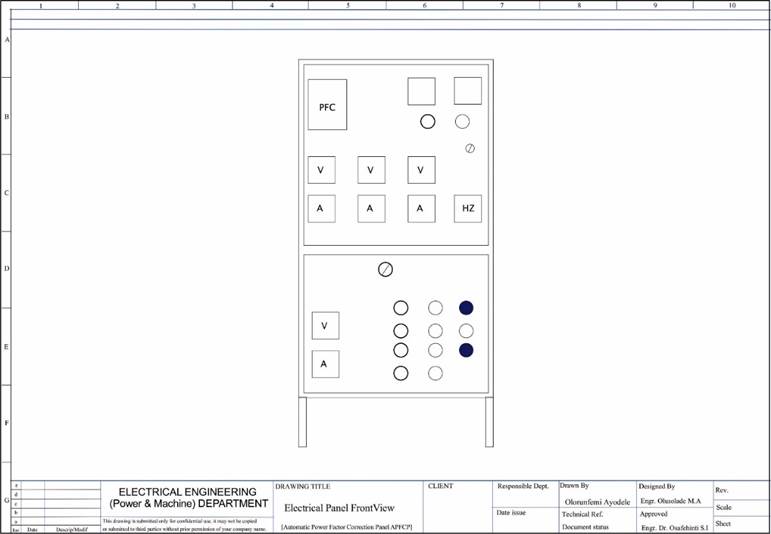
|
Figure 1 Front View of 625 kVAR Capacitor Bank |
Figure 2
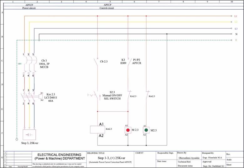
|
Figure 2 Power and Control Circuit for Steps 1 – 3 Selection |
Figure 3
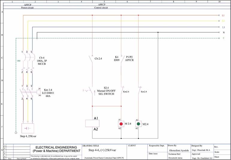
|
Figure 3 Power and Control Circuit For Step 4 – 6 Selection |
STEP 6: Selection of Molded Case Circuit Breaker (MCCB)
Before deciding on the choice of circuit breaker needed to protect any circuit, three main criteria need to be considered. They are:
1) The rated working voltage (Ve) of the MCCB must be similar to the system voltage.
2) The trip value of the MCCB should be adjusted according to the current drawn by the load.
3) The breaking capacity must be higher than the theoretical possible fault currents.
Having considered the above factors using formula: Power, P = √3 × V × I × Cos Ɵ.
Since Power P, P = 500KW, Voltage, V = 415Volts and Cos Ɵ = 0.99
Substituting in the above values into given formula: P = √(3× V × I × Cos Ɵ )
500,000 = √(3 x 415 x I x 0.99)
Current, I = 500,000/√(3 x 415 x I x 0.99)
500,000/711.613 = 702.629 Amps.
Since there is no circuit breaker rated exactly 702.629 Amps in the market, we opted for 800 Amps circuit breaker.
Selection of miniature circuit breaker (mcb) for 50kVAR capacitor each was done using manufacturer’s chart, 100 Amps mcb was selected to protect each of the six steps.
STEP 7: Selection of Capacitor Duty Contactor
Selection Table according to IEC
80 Amps contactor was selected for the capacitor duty contactor from the above selection table.
STEP 8: Selection of Auto Power Factor Controller
Seven steps programmable auto power factor controller manufactured by Federal was purchased in the local market for this project. Through design calculation, only six capacitors of 50kVAR each was used. Only six of the seven terminals were connected.
Figure 4
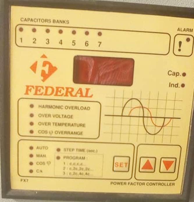
|
Figure 4 Power Factor Controller |
4. CONCLUSION
This connection of the 300KVAR brought about reduced losses and hence reduced heating in switch gears, transformer, cables, and electric motors. Also, reduction in reactive power demand from the supply improved voltage regulation.
CONFLICT OF INTERESTS
None.
ACKNOWLEDGMENTS
None.
REFERENCES
Glover, J. D., and Sarma, M. S. (2002).
"Power System Analysis and Design " (3rd ed.). Wadsworth Group,
Brooks Cole, a Division of Thompson Learning Inc.
Menta, V. K., and Menta, R. (2004)."Principles of Power System " (1st ed.). S. Chand &
Company Ltd.
Michael, O., and Kolawole et al,
(2012). Basic Electrical Engineering. Aoge, Nigeria
Limited.
Pabla, A. S. (2003). "Electric Power Distribution" (4th ed.). Sixth Reprint,
Tata McGraw -Hill Pub. Comp. Ltd.
Thereja, B. L., and Thereja, A. R. (2002). "Electrical Technology" Revised Edition, S. Chand & Company Ltd.
 This work is licensed under a: Creative Commons Attribution 4.0 International License
© Granthaalayah 2014-2023. All Rights Reserved.