MODIFYING RESIN VISCOELASTICITY BY MULTIFUNCTION CAVITATION PROCESSING IN A MAGNETIC FIELD
Toshihiko Yoshimura 1![]() , Seijiro Fujinaga
1, Masataka
Ijiri 2
, Seijiro Fujinaga
1, Masataka
Ijiri 2![]()
1 Department of Mechanical Engineering, Sanyo-onoda
City University, 1-1-1 Daigaku-dori, Sanyo-Onoda, Yamaguchi 756-0884 Japan
2 Department
of Mechanical Systems Engineering, Tokyo Metropolitan University, 1-1 Minami-Osawa, Hachioji, Tokyo 192-0397, Japan
|
|
|
ABSTRACT |
|
|
The viscoelastic
properties of polyamide 11 samples were modified by subjecting these
specimens to multifunction cavitation within a magnetic field, using a device
equipped with a 0.1 mm water jet nozzle. During these trials, a magnetic
field was applied to the entire water jet stream while varying the distance
between the nozzle and the specimen. The effects of various processing
conditions were assessed by monitoring the removal of ink applied to sample
surfaces. The results obtained using this technique with and without a
magnetic field were also evaluated. |
|||
|
Received 01 June 2022 Accepted 07 July 2022 Published 26 July 2022 Corresponding Author Toshihiko
Yoshimura, DOI 10.29121/IJOEST.v6.i4.2022.364 Funding: This research
received no specific grant from any funding agency in the public, commercial,
or not-for-profit sectors. Copyright: © 2022 The
Author(s). This work is licensed under a Creative Commons
Attribution 4.0 International License. With the
license CC-BY, authors retain the copyright, allowing anyone to download,
reuse, re-print, modify, distribute, and/or copy their contribution. The work
must be properly attributed to its author.
|
|||
|
Keywords: Magnetic Field
Multifunction Cavitation, Polyamide, Viscous Elasticity |
|||
1. INTRODUCTION
Cavitation is a physical phenomenon in which bubbles are generated and disappear in a short time due to the presence of a pressure differential in a liquid flow. This phenomenon was discovered at the end of the 19th century when propellers for high-speed ships did not perform as expected. Therefore, cavitation was originally regarded as undesirable but has since become useful industrially. Various terms may be used for this process but in each case the same phenomenon occurs in which a gas phase cavity is formed in a liquid. In the case of relatively large bubbles (those having a radius of up to several hundred micrometers), decay of the microjet becomes dominant and both mechanical and electrochemical processing can be performed. In contrast, ultrasonic cavitation, and micro-nano bubbles (with sizes of 10 μm or less) enable chemical processing and promote chemical reactions Agarwal et al. (2011)
Nylon is a polyamide polymer that is widely used in daily life. Nylon is often found in clothing and miscellaneous goods, although 35-40% of this polymer is employed in the fabrication of automobiles. When a force is applied to a macromolecular material such as this, a stress resulting from the elastic strain is instantaneously generated, while viscous strain also occurs over time due to displacement between polymer chains. This phenomenon by which both elasticity and viscosity are exhibited is known as viscoelasticity. Because the polymer chains pull against one another as they move, as a result of van der Waals forces, a stress due to elastic strain is generated based on changes in bond angles at the moment at which the force is applied. If the force is continuously applied, viscous strain (otherwise known as shear yield strain) is generated at the same time as elastic strain as a consequence of the displacement of polymer chains. If the force is subsequently removed, the elastic strain is restored but the viscous strain is not and remains as a permanent strain. Various properties of polymers, including wettability, adsorption, adhesion, bond ability, dyeability, water repellency and wear resistance are primarily dependent on the composition of the material near the surface. Thus, the properties of plastics can be modified using techniques such as excimer laser irradiation Okoshi and Murahara (1998) Sato and Murahara (2012) and photo immobilization Ito et al. (2007)
Our own group previously developed a multifunction cavitation (MFC) technique that demonstrates characteristics corresponding to both ultrasonic cavitation Nagata et al. (1992) and water jet cavitation Yoshimura et al. (2016) Yoshimura et al. (2018a) (International PCT published patent WO2016136656A1, US registered patent, Inventor: Toshihiko Yoshimura, Assignee: Sanyo-Onoda City Public University, US Patent No. 10,590,966 B2, Date of Patent: Mar. 17, 2020). The bubble temperature and pressure obtained during MFC were later improved by employing a swirl addition nozzle Yoshimura et al. (2018b) In the case of the ultra-high-temperature and high-pressure cavitation method Yoshimura et al. (2018a) Yoshimura et al. (2021a) a water jet flow associated with water jet cavitation is irradiated with ultrasonic waves from one direction. We have also demonstrated an energy-intensive MFC (EI-MFC: Energy Intensive Multifunction Cavitation) technology in which ultrasonic waves are applied from the circumferential direction of the jet flow Yoshimura et al. (2021b) In addition, the charged bubble phenomenon that occurs during MFC Yoshimura et al. (2016) Yoshimura et al. (2018a) has been employed to devise a concentrated energy MFC technology involving the application of a strong magnetic field (MEI-MFC: magnetic energy intensive multifunction cavitation) Yoshimura et al. (2022) This technique uses a large-scale apparatus with a water jet nozzle diameter of 0.8 mm and a flow rate of approximately 7 L/min that generates larger bubbles with radii of up to several hundred micrometers. Although this process is suitable for the surface modification of metals, its application to the synthesis of photocatalyst powders or similar materials is time consuming and does not allow the generation of high-purity products.
For these reasons, our group also constructed a smaller MFC apparatus incorporating a water jet with a nozzle diameter of 0.1 mm and using a flow rate of approximately 160 mL/min Yoshimura et al. (2021c) In prior research, the photons emitted from MFC bubbles generated in this small-scale apparatus as a result of sonoluminescence were monitored Yoshimura et al. (2021c). The bubble size was determined to be 10 μm or less but the bubble temperature was increased to the same value as was obtained using the larger equipment Yoshimura et al. (2021d). Previous work also established that the application of a magnetic field to this reduced-size MFC equipment using neodymium magnets activated the charged MFC bubbles while increasing the number of bubbles Yoshimura et al. (2021e), Yoshimura et al. (2022)
The present study employed MFC in conjunction with a magnetic field (M-MFC) and investigated the effects of various parameters (specifically, the nozzle-resin distance and the presence of magnets) while processing samples of the thermoplastic resin polyamide 11 using a small-scale MFC apparatus Yoshimura et al. (2022). Both these parameters were optimized and, using these optimized conditions, the ability of high-temperature and high-pressure M-MFC processing to reduce the surface viscoelasticity of the polyamide 11 was evaluated.
2. EXPERIMENTAL
2.1. FILM PEELING TEST FOR VISCOELASTICITY EVALUATION
Figure 1 provides a diagram of the M-MFC apparatus. In this process, a high-pressure water jet is generated from a 0.1 mm diameter water jet nozzle at a flow rate of 160 mL/min and a pressure of 40 MPa Yoshimura et al. (2021d), Yoshimura et al. (2021e). The sound pressure generated by the ultrasonic irradiation varies and bubbles that exceed the Blake threshold Atchley (1989) will undergo repeated isothermal expansion and adiabatic compression Rayleigh (1917) Plesset (1949) with the formation of hot spots Gompf et al. (1997) to provide high-temperature, high-pressure MFC Yoshimura et al. (2016) Yoshimura et al. (2018a). The Blake threshold is the sound pressure required for a bubble to expand and has a value of approximately 1 ATM for a bubble size of several micrometers or more. However, if the bubble is in rapid motion, the Blake threshold increases. During MFC in the presence of a magnetic field, the charged bubbles will collide while driven by the Lorentz force and the number of high-temperature, high-pressure bubbles will increase Yoshimura et al. (2021e), Yoshimura et al. (2022). In the present study, the structure of the water tank Yoshimura et al. (2021d), Yoshimura et al. (2022) used in the reduced-size MFC apparatus was improved to make observations of the process easier. Prior to this improvement, viewing port ICF70, which comprised a vacuum flange, was attached facing perpendicular to the ultrasonic transducer. However, because this port was too small to allow direct observations, three large viewing ports (ICF114) were added in the present work: one horizontal to the direction of ultrasonication and two vertical. In addition, four strong neodymium permanent magnets (Sangyo Supply Co., Ltd., N40) were placed on the upper part of the ICF114 flange near the nozzle exit. Similarly, four magnets were placed at the bottom of the ICF114 flange (meaning eight in total). A magnetic circuit was constructed from the right side of the apparatus to the north pole and from the left side to the south pole such that a magnetic field was formed over the entire jet flow. The strength of this field ranged from 0.75 MT near the nozzle outlet to 1.0 MT in the cavitation cloud, where the largest number of bubbles was generated. These experiments used a magnetometer (MG-3003SD) with a magnetic meter and SD card data recorder (A-Gas Japan Co., Ltd.) to measure the magnetic flux. This magnetometer had a measurement range (DC) and display resolution of 300 MT and 0.01 MT (range 1) or 3000 MT and 0.1 MT (range 2), respectively, and was highly accurate.
Figure 1
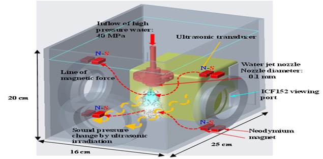
|
Figure 1 Diagram of laboratory-scale MFC apparatus incorporating neodymium magnets |
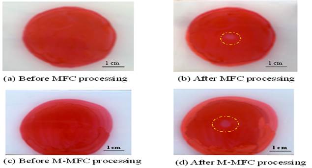
In the case that two neodymium magnets were placed at the base of the equipment near the nozzle outlet, the magnetic flux density at the outlet was 0.23 MT Yoshimura et al. (2022) and the jet flow spread out from the middle. As such, the entire water jet was activated by the collision of charged bubbles and the number of bubbles was increased in the high magnetic field generated by the eight magnets. Ink peeling tests were performed to confirm this increase in the quantity of bubbles and the corresponding improvement in processing capacity. In these trials, polyamide 11 specimens were marked with a Pilot Red whiteboard marker and then allowed to dry for two days. These samples were subsequently subjected to MFC processing with and without magnets while also varying the distance between the nozzle and the resin. Pure water (having a resistance of 15 MΩ) was used in these trials. Figure 2 shows photographic images of the apparatus and specimen during the peeling tests while Table 1 summarizes the processing conditions. During both MFC and M-MFC trials, the processing time was 10 min and the distance between the nozzle and sample (the stand-off distance) was either 3, 7 or 37.5 mm.
Figure 2
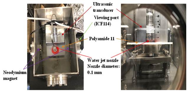
|
Figure 2 Photographic images of laboratory-scale MFC apparatus incorporating neodymium magnets in which the plate of polyamide 11 is place |
Table 1
|
Table 1 Experimental conditions applied during peeling tests |
||||
|
No. |
Number of magnets |
Processing time (min) |
Standoff distance (mm) |
|
|
1 |
MFC |
0 |
10 |
3 |
|
2 |
M-MFC |
8 |
10 |
3 |
|
3 |
MFC |
0 |
10 |
7 |
|
4 |
M-MFC |
8 |
10 |
7 |
|
5 |
MFC |
0 |
10 |
37.5 |
|
6 |
M-MFC |
8 |
10 |
37.5 |
2.2. CHANGES IN THE VISCOELASTICITY OF POLYAMIDE 11 BY M-MFC
Table 2 summarizes the experimental conditions during trials intended to modify the viscoelasticity of the polyamide 11 samples while Figure 3 presents a photographic image of the M-MFC processing corresponding to the set of conditions given number 6 in Table 1 In this process, the bubbles collided with each other as a consequence of the magnetic field and an increased number of bubbles contacted the surface of the specimen and subsequently flowed in the horizontal direction. For comparison purposes, processing was also performed using the processing conditions shown in entry 5 in Table 1
Figure 3
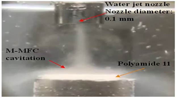
|
Figure 3 Photographic image of the processing of polyamide 11 by M-MFC |
Table 2
|
Table 2 Experimental parameters during the MFC and M-MFC processing of polyamide 11 |
||||
|
No. |
Processing method |
Number of magnets |
Processing time (min) |
Standoff distance (mm) |
|
1 |
MFC |
0 |
10 |
37.5 |
|
2 |
M-MFC |
8 |
10 |
37.5 |
The viscoelasticity of each polyamide 11 sample was measured using an AFM5200S instrument (Hitachi High-Tech Science Corp.) operating in the viscoelastic dynamic force mode (VE-DFM). The DFM assesses surface morphology while controlling the distance between a probe and the sample so that the vibrational amplitude of the cantilever becomes constant while the cantilever is resonating. Atomic force microscopy (AFM) involves scanning while vibrating the sample in the vertical direction, during which deflections are determined by the viscoelasticity of the sample surface. In the case of VE-AFM, a lock-in measurement is carried out and the deflection of the vibrations provides the distribution of viscoelasticity. In the case of a hard sample, the vibrational amplitude of the cantilever is large, and the fluctuations of the sample vibrations are minimal. In contrast, the vibrational amplitude of the cantilever will be small when assessing a soft sample and the deformation amplitude of the sample will be large. In this technique, the input signal related to longitudinal vibrations applied from the scanner side is distributed as an output signal related to the deflection vibration of the cantilever and the fluctuation vibration of the sample, based on the viscoelastic action of the tip of the probe and the sample. As the sample hardness increases, the cantilever vibrations will become greater as a result of reduced deformation of the sample. If the sample is soft, sample deformation vibrations will be induced, and the cantilever vibration will be decreased. The lock-in amplifier detects the elastic component, Acosδ, which is synchronized with the scanner vibration, and the viscous component, Asinδ, whose phase is delayed by 90°. The amplitude component, A, is imaged to provide the viscoelastic distribution based on the square root of the sum of squares.
In the present study, geometric assessments were performed with the apparatus in the DFM, and trace scanning was carried out in the VE-AFM while moving the probe over a specific distance from the DFM surface scan line. This process generated a viscoelastic distribution. The shape of each sample was evaluated in this manner by scanning from left to right while monitoring the height, h, of the probe relative to the surface height, ho. The probe subsequently returned to the same line and, when employing the VE-DFM, the excitation of the scanner cantilever (PZT: lead zirconate titanate) was stopped. At this point, the probe height was increased or decreased by h = h0 + ht and AFM was used to trace the sample morphology. In the case that ht > 0, the probe and the sample were not in contact, which is meaningless in the VE-DFM. Conversely, at ht < 0, the trace height was adjusted to be lower than the original vibrational amplitude of the cantilever, such that the tip of the probe came into contact with the sample and the viscoelastic response could be measured. This scanning process was carried out for each line and the shape signal (acquired in the DFM) and the viscoelastic signal (obtained using AFM) were obtained in an alternating manner.
3. EXPERIMENTAL RESULTS
3.1. FILM PEELING TEST FOR VISCOELASTICITY EVALUATION
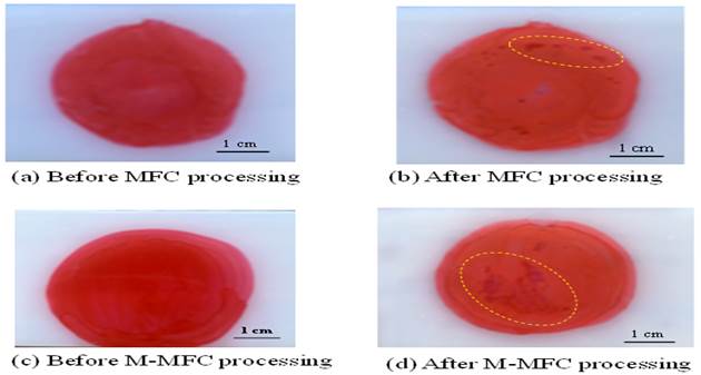
Figure 4 presents photographs of the specimens before and after processing with and without the eight magnets in place, applying a stand-off distance of 3 mm. Slight processing marks can be seen in the center of each specimen after both MFC and M-MFC processing, indicating that the magnetic field did not provide any additional effect. This result is attributed to the narrow jet contact area used in these trials, as a result of the short distance from the nozzle to the resin, such that peeling occurred before the MFC process was activated.
Figure 4
|
Figure 4 Photographic images of specimens following peeling tests using MFC and M-MFC processing with a stand-off distance of 3 mm and eight magnets |
Figure 5 presents the results of peeling experiments carried out with and without the magnets at a standoff distance of 7 mm. These images indicate peeling at the peripheral parts of the specimens even in the absence of the magnetic field. It is evident that isothermal expansion and adiabatic compression of bubbles occurred such that MFC processing was performed. Figure 5 also shows that the magnetic field increased the degree of peeling, meaning that the process was improved by activating the MFC owing to the Lorentz force.
Figure 5
|
Figure 5 Photographic images of specimens following peeling tests using MFC and M-MFC processing with a stand-off distance of 7 mm and eight magnets |
Figure 6 compares the results of MFC and M-MFC processing with a stand-off distance of 37.5 mm, again using eight magnets. Compared with the results obtained at a stand-off distance of 7 mm shown in Figure 5 the photograph in Figure 6 demonstrates more extensive peeling. This effect is attributed to the collisions of bubbles with the sample.
Figure 6
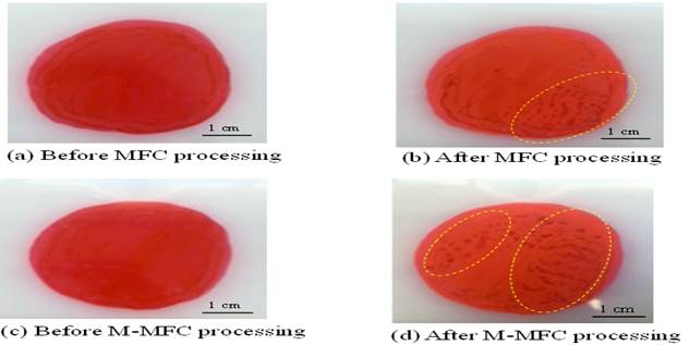
|
Figure 6 Photographic images of specimens following peeling tests using MFC and M-MFC processing with a stand-off distance of 37.5 mm and eight magnets |
3.2. CHANGES IN THE VISCOELASTICITY OF POLYAMIDE 11 BY M-MFC
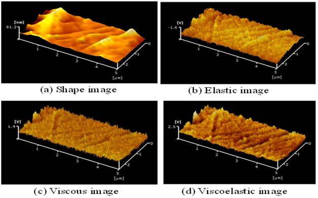
Figure 7 presents shape elastic, viscous and viscoelastic images of unprocessed specimens acquired in the VE-DFM. Note that the signal has been magnified in each case by a factor of 10. Various linear scratches and protrusions can be seen on the surface, corresponding to lower viscosity, elasticity, and viscoelasticity values.
Figure 7
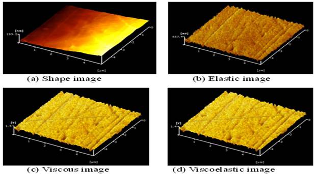
|
Figure 7 VE-DFM images obtained for unprocessed samples at a 10× magnification |
Figure 8 provides the same images for specimens after processing. Large dents corresponding to peening marks are evident as a consequence of the MFC treatment. The elasticity, viscosity and viscoelasticity are generally lower at these locations.
Figure 8
|
Figure 8 VE-DFM images obtained from a processed sample at 10× magnification |
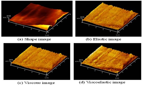
Figure 9 shows VE-AFM images obtained from the M-MFC processed material. Here, the signal magnification is 50 times, which is higher than that in Figure 7 and Figure 8 It is apparent that there were protruding regions on the surface, but the elasticity, viscosity and elasticity were low in these areas. In addition, the vertical axis of the elastic image is negative, indicating that the elasticity was significantly reduced by M-MFC processing.
Figure 9
|
Figure 9 VE-DFM images obtained from a processed sample at 50× magnification |
The arithmetic mean surface roughness prior to processing was 4.31 nm and increased to 10.80 nm after MFC processing but remained essentially constant at 4.34 nm after M-MFC processing. The M-MFC treatment appears to have flattened the sample surface, presumably because the specimen was heated above its melting point and so was annealed. The application of EI-MFC or MEI-MFC (during which concentrated energy is generated) to a soft metal such as pure aluminum has been found to generate deep surface holes and irregularities with dimensions of several micrometers, which primarily correspond to peening marks Yoshimura et al. (2022) This difference is largely due to the difference between the structure of a metal and that of the high molecular weight polymer used in the present work. In addition, because both EI-MFC and MEI-MFC employ a nozzle with a diameter of 0.8 mm, the bubble size can be as large as 100 μm. Thus, the impact force imparted by the microjet at the time of bubble collapse Kling (1970) Summers (1987) as well as the impact area are greater. In contrast, in the case of the 0.1 mm diameter nozzle used in the present experiments, the bubble size was as small as several micrometers. Consequently, the impact force and the area of the shock wave of the microjet at the time of bubble collapse were both reduced, which is one reason why the surface was not roughened.
Figure 10 summarizes the changes in elasticity with processing. This graph plots the average elasticity values and the corresponding standard deviations obtained by analysing a number of images of various samples. The elasticity evidently decreased after MFC processing but decreased even further (to negative values) following M-MFC processing.
Figure 10
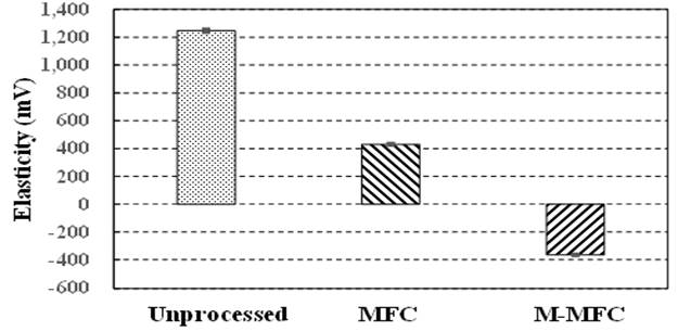
|
Figure 10 Elasticity values for polyamide 11 specimens after various processing trials |
Figure 11 and Figure 12 show the results of viscosity and viscoelasticity assessments of samples subjected to either MFC or M-MFC processing. In both cases, the value was reduced after treatment. Both procedures therefore flattened and softened the sample surface. Elastic strain is time-independent whereas viscous strain is time-dependent, and so the time span over which stress or strain is applied must be considered when designing plastic products. For this reason, changing the cavitation processing time affected the viscosity. The viscoelasticity of the polyamide 11 could be modified by varying the processing time, reducing the water jet discharge pressure from 40 MPa, and adjusting the strength of the magnetic field. In addition, polyamide 11 is not a biopolymer or a biodegradable plastic. When a biopolymer such as polybutylene terephthalate or a resin such as polyethylene or polyethylene terephthalate is subjected to M-MFC processing, the viscoelasticity of the surface is reduced while the viscous strain remains. The energy applied during M-MFC may also increase the extent to which the polymer can be decomposed.
Figure 11
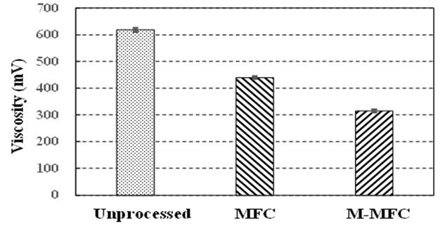
|
Figure 11 Viscosity values for polyamide 11 specimens after various processing trial |
Figure 12
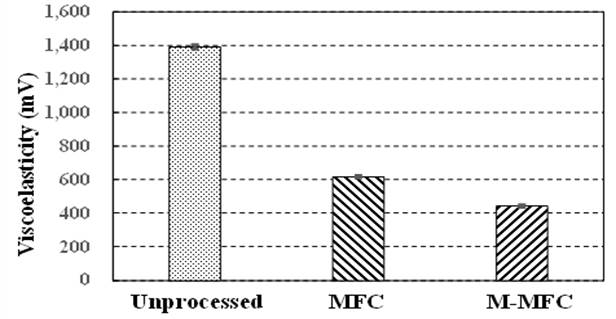
|
Figure 12 Viscoelasticity values for polyamide 11 specimens after various processing trials |
4. CONCLUSION
A small multifunction cavitation apparatus incorporating a magnetic field together with a 0.1 mm water jet nozzle was used to modify the viscoelasticity of polyamide 11. By applying ink to the surface of various specimens, the effect of the stand-off distance between the nozzle and the sample was determined based on the extent of degradation of the surface. The data also indicated that the surface roughness of the polymer was increased by MFC processing, but the M-MFC technique provided additional flattening of the resin surface. M-MFC was found to reduce the elasticity of the polyamide along with the viscosity and viscoelasticity, while also softening the surface. Finally, adjusting the M-MFC parameters was shown to permit tuning of the viscoelasticity of the polyamide 11 surface.
Acknowledgement
This research was supported in part by a JSPS KAKENHI Grant-in-Aid for Scientific Research (C) (no. 19K04110).
REFERENCES
Agarwal, A. Ng, W. J. Liu, Y. (2011). Principle and applications of micro bubble and nano bubble technology for water treatment. Chemosphere, 84(9), 1175-1180. https://doi.org/10.1016/j.chemosphere.2011.05.054
Atchley, A. (1989). The Blake threshold of cavitation nucleus having a radius-dependent surface tension, 85(1), 152-157. https://doi.org/10.1121/1.397724
Gompf, B. Gunther, R. Nick, G. Pecha, R. Eisenmenger, W. (1997). Resolving sonoluminescence pulse width with time-correlated single photon counting. 79, 1405-1408. https://doi.org/10.1103/PhysRevLett.79.1405
Ito, Y. Hasuda, H. Sakuragi, M. Tsuzuki, S. (2007). Surface modification of plastic, glass and titanium by photoimmobilization of polyethylene glycol for antibiofouling. Acta Biomaterialia, 3, 1024-1032. https://doi.org/10.1016/j.actbio.2007.05.010
Kling, C. L. (1970). A High speed photographic study of cavitation bubble collapse. University Michigan Report No.
Nagata, Y. Watanabe, Y. Fujita, S. Dohmaru, T. Taniguchi, S. (1992). Formation of colloidal silver in water by ultrasonic irradiation. Journal of the Chemical Society, Chemical Communications, 21, 1620-1622. https://doi.org/10.1039/c39920001620
Okoshi, M. Murahara, M. (1998). Area-selective nucleation of copper on fluorocarbon-resin surface using ArF excimer laser-induced chemical modification. Applied Physics Letters, 72(20), 2616-2618. https://doi.org/10.1063/1.121435
Plesset, M. W. (1949). The dynamics of cavitation bubbles. Journal of Applied Mechanics, 16277-16282. https://doi.org/10.1115/1.4009975
Rayleigh, L. (1917). On the pressure developed in a liquid during the collapse of a spherical cavity. Philosophical Magazine, 34(200), 94-98. https://doi.org/10.1080/14786440808635681
Sato, Y. Murahara, M. (2012). Protein adsorption on PTFE surface 1nodified by ArF exci1ner laser treatment. Journal of Adhesion Science and Technology, 18(3), 1545-1555. https://doi.org/10.1163/1568561042411259
Summers, D. (1987). Consideration in the design of a waterjet device for reclamation of missile casings. Proc of the 4th U.S. Water Jet Conference, The University of California, Berkeley, 82-89.
Yoshimura, T. Ijiri, M. Sato, K. (2021e). Estimation of Nuclear Fusion Requiremensts in Bubbles During Ultra-high-pressure, Ultra-high-temperature Cavitation Promoted by Magnetic Field. International Journal of Engineering Science Technologies, 5(6), 102-115. https://doi.org/10.29121/ijoest.v5.i6.2021.257
Yoshimura, T. Iwamoto, M. Ogi, T. Kato, F. Ijiri, M. Kikuchi, S. (2021a). Peening Natural Aging of Aluminum Alloy by Ultra-High-Temperature and High-Pressure Cavitation. Applied Sciences, 11(2894), 1-13. https://doi.org/10.3390/app11072894
Yoshimura, T. Nishijima, N. Hashimoto, D. Ijiri, M. (2021c). Sonoluminescence from ultra-high temperature and pressure cavitation produced by a narrow water jet. Heliyon, 7(8), 1-8. https://doi.org/10.1016/j.heliyon.2021.e07767
Yoshimura, T. Shimonishi, D. Hashimoto, D. Nishijima, N. Ijiri, M. (2021d). Effect of Processing Degree and Nozzle Diameter on Multifunction Cavitation. Surface Engineering and Applied Electrochemistry, 57(1), 101-106. https://doi.org/10.3103/S1068375521010154
Yoshimura, T. Sugae, Y. Ogi, T. Kato, F. Ijiri, M. (2021b). Development of energy intensive multifunction cavitation technology and its application to the surface modification of the Ni-based columnar crystal superalloy CM186LC. https://doi.org/10.1016/j.heliyon.2021.e08572
Yoshimura, T. Tanaka, K. Ijiri, M. (2018b). Nanolevel surface processing of fine particles by waterjet cavitation and multifunction cavitation to improve the photocatalytic properties of titanium oxide. https://doi.org/10.5772/intechopen.79530
Yoshimura, T. Tanaka, K. Yoshinaga, N. (2016). Development of mechanical-electrochemical cavitation technology, Journal of jet flow engineering, 32, 10-17.
Yoshimura, T. Tanaka, K. Yoshinaga, N. (2018a). Nano-level Material Processing by Multifunction Cavitation. Nanoscience & Nanotechnology-Asia, 8(1), 41-54.
Yoshimura, T. Watanabe, S. Ijiri, M. Ota, S. (2022). Development of processing technology using extremely high concentration cavitation energy by strong magnetic field. Results in Materials, 14, 1-11. https://doi.org/10.1016/j.rinma.2022.100289
 This work is licensed under a: Creative Commons Attribution 4.0 International License
© Granthaalayah 2014-2022. All Rights Reserved.