
|
|
|
|
VIBRATION ANALYSIS OF THE TOOL BEARING SPINDLE IN CASE OF SUPERFINISHING TECHNOLOGIAL PROCESSES ESTABLISHMENT OF THE GENERAL MOVEMENT EQUATIONS
Daniel Popescu *1
|
|
|
|


Article Type: Research Article
Article Citation: Daniel Popescu. (2020). VIBRATION ANALYSIS OF THE TOOL BEARING SPINDLE IN CASE OF SUPERFINISHING TECHNOLOGIAL PROCESSES ESTABLISHMENT OF THE GENERAL MOVEMENT EQUATIONS. International Journal of Research -GRANTHAALAYAH, 8(5), 339 – 347. https://doi.org/10.29121/granthaalayah.v8.i5.2020.222
Received Date: 18 May 2020
Accepted Date: 31 May 2020
Keywords:
Superfinishing
Main Spindle
Eccentric
Vibrations
Movement Equations
ABSTRACT
The paper presents a mathematical model for determining the general movement equations that describe the vibration movement of the tool bearer spindle at superfinishing operations. There are presented the specific problems and the work schematics. The mathematical model uses the axioms of kinetic impulse and moment derivatives. At superfinishing, the spindle is eccentric and its working position is vertical. A series of simplifying assumptions are used, such as: Bernoulli’s hypothesis, the movement is without shocks, there are no remnant tensions, the strains are of elastic nature only. There are emphasized the components of the movement equations under restricted matrix form. The effect of transversal contraction and the torsion vibrations are neglected.
1. INTRODUCTION
Superfinishing represents a micro finishing technique that uses abrasive bars, executed on special machines which provide complex movements at reduced grinding speeds and pressures, in the presence of greasing-cooling liquids. Thus, are processed external and internal cylindrical, plane and complex surfaces.
In such processing, the piece bearer surface increases up to 90%, leading from high pressures on small surfaces to small pressures on large surfaces, such that the lubricating shell between tool and piece can no longer be penetrated without stopping the grinding process.
The work schematic and its component elements are presented in figure 1.
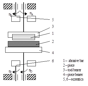
Figure 1: Superfinishing processing schematic
2. METHODOLOGY
In order to determine the initial conditions in which evolves the proposed mathematical model, and which determine the general movement equations, a series of simplifying assumptions is adopted, such as [1]: the spindle works only in a given environment; there are no shocks during movement; the strains on the spindle are of elastic nature only; Bernoulli’s hypothesis is true.
The proposed spindle model is given in figure 2.
In this case, the main spindle is related to two reference systems:
· (T0) - external reference, considered fixed
· (T) - proper reference attached to the spindle
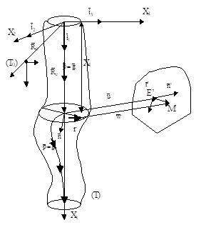
Figure 2: Model for the main spindle ued in case of superfinishing operation
3. FINDINGS AND DISCUSSION
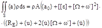
Considering the equations given by the Hamilton’s principle, we have:
![]()
![]() (1)
(1)
Where:
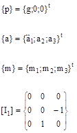
{a} - matrix corresponding to acceleration of the current point of the spindle section
{p} - matrix of the linearly distributed load on the spindle axis
{T} - matrix corresponding to the resulting force of tensions in the spindle section
{M} - matrix corresponding to the resulting moment of tensions in the spindle section
 (2)
(2)
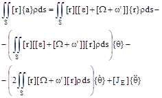
The movement equations become:
![]() (3)
(3)
Where:
![]()
![]()
![]() (4)
(4)
Based on the analysis of the inertial terms, on the computation of resulting force and moment of the tensions in section, we can obtain the movement equations under the form [2],[3]:
![]() (5)
(5)
Where:
![]() ;
; 
![]()
![]() ;
; ![]()
![]() ;
; ![]()
![]() (6)
(6)
in Which
 (7)
(7)
And
 (8)
(8)
Where:
![]()
![]()
![]()
![]()
![]()
![]()
![]()
![]()
 (9)
(9)
in Which:

 (10)
(10)
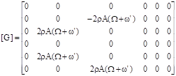
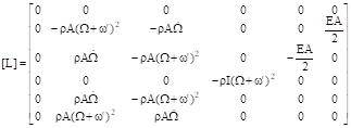
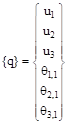
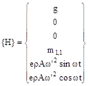
Under reduced matrix form, (5) and (7) become [4],[5]:
![]() (11)
(11)
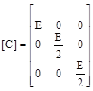
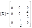
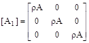
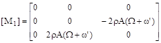
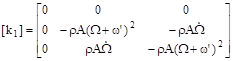
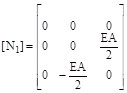
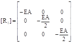
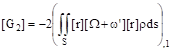
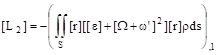
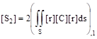
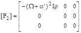
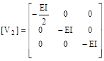
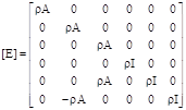
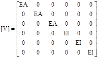
Where:
![]()
![]()
![]()
![]()
![]()
![]() `
(12)
`
(12)
 (13)
(13)
Observations:
ω’ represents the constant angular velocity of the eccentric spindle;
the transversal contraction is ignored (n = 0);
there is no torsion vibration (q1 = 0);
 (14)
(14)
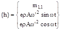
Observations:
e represents spindle eccentricity;
![]() (Bernoulli
effect).
(Bernoulli
effect).
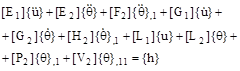
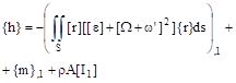
The general equations of the vibration movement are:
![]()
![]()
![]() (15)
(15)
4. CONCLUSIONS AND RECOMMENDATIONS
· In order to establish the general equations of the vibration movement of the main spindle at superfinishing, it is employed Hamilton’s variation principle.
· There are also taken into account the specific conditions given by the eccentric shape of the main spindle which rotates with constant angular speed ω’.
· Establishment of the movement equations is performed under simplifying assumptions that define the initial conditions of the movement.
· Thus, are created the premises for inserting the external strains and for determining the balance configuration.
SOURCES OF FUNDING
None.
CONFLICT OF INTEREST
None.
ACKNOWLEDGMENT
None.
REFERENCES
[4] Moraru, V., Ispas, C., Vibrations and Machine Tools Stability, EDP, 1982.
|
|
 This work is licensed under a: Creative Commons Attribution 4.0 International License
© Granthaalayah 2014-2020. All Rights Reserved.