Development of a Didactic Simulator for Water Treatment Systems
Armando J. L. Cordeiro 1![]() , Miguel C. L. Almeida 2
, Miguel C. L. Almeida 2![]() , Maria G. V. B. Almeida 3
, Maria G. V. B. Almeida 3![]()
1,2,3 Departmental
Area of Electrical Engineering Energy and Automation (ADEEEA) Instituto
Superior de Engenharia de Lisboa (ISEL), IPL Lisbon, Portugal
|
|
|
ABSTRACT |
|
|
This paper
presents the implementation of a didactic simulator for industrial automation
supported by a supervision system. As a result of this work, a solution based
on a system of six reservoirs was developed, together with a supervision
system that allows the simulator to be controlled and monitored through a
Raspberry Pi with a touch screen display and an android application. The aim
of this work is to develop a system that can be used by other undergraduate
and master's students of the electrical engineering course at ISEL, for them
to deepen their knowledge in automation. It is also intended that the
simulator be used in fairs, exhibitions, and open days to internal and
external students at ISEL, showing some of the work that has been developed
in the master’s degree in electrotechnical engineering, especially in the
field of industrial automation. |
|||
|
Received 30 May 2022 Accepted 05 July 2022 Published 22 July 2022 Corresponding Author Armando
J. L. Cordeiro, acordeiro@deea.isel.ipl.pt DOI 10.29121/granthaalayah.v10.i7.2022.4685 Funding: This research
received no specific grant from any funding agency in the public, commercial,
or not-for-profit sectors. Copyright: © 2022 The
Author(s). This work is licensed under a Creative Commons
Attribution 4.0 International License. With the
license CC-BY, authors retain the copyright, allowing anyone to download,
reuse, re-print, modify, distribute, and/or copy their contribution. The work
must be properly attributed to its author.
|
|||
|
Keywords: Automation, SCADA, Water Treatment Plants,
Communication, Teaching in Automation |
|||
1. INTRODUCTION
Over the last few decades, we have observed a fast growth of new technological solutions in many fields of activity. In the field of industrial automation, a great progress has been made because of the emergence of new production techniques using new equipment. These technological advances, among others, have brought, over the last decades, an increasing flexibility and complexity to automated processes.
Industrial automation is currently a multidisciplinary area that requires engineers to have extensive knowledge in areas related to electrical engineering, such as mechanics, computing, or electronics. That’s because almost all existing industrial equipment currently has numerous power circuits with electronic regulation and with the possibility of programming at different levels. These changes in industrial automation (and in many other areas) represent a high challenge for the various educational institutions because it’s necessary to provide their students with the right tools to maintain and operate these modern equipment’s without forgetting the principles and fundamentals laws of physics and mathematics by which this work.
The work presented in this paper is a didactic simulator of industrial automation supported by a supervision system that meets some of the educational needs in terms of industrial automation, with regards to programmable controllers, communication networks in environments industrial and supervision systems.
2. EDUCATION IN ENGINEERING
Education is one of the most important pillars of society and should be treated as such. The technological advances of the last decades, especially those introduced by Industry 4.0 have allowed several opportunities for the engineer's role in society. However, in order to keep the technical skills of future engineers up to date and maintain the training of good professionals, a successive remodelling of engineering education is necessary Shuman et al. (2002) In 2002, on the journal Issues in Science and Technology, WM. A. WULF e GEORGE M. C. FISHER wrote that “[…] students are being prepared to practice engineering for their parents' era, not for the 21st century.” Wulf and Fisher (2002)
Several papers Lima et al. (2017), Pereira et al. (2012), Chaos et al. (2013), Naumovic and Zivanovic (2008), Ma and Nickerson (2006) mention that laboratories, due to their practical approach to the theoretical contents, allow a better consolidation of this, preparing students for what companies are looking for in an engineer. However, most of the laboratory teaching material available are expensive to acquire and maintain and aren't very versatile. There's also a lack of qualified human resources and time for material planning. To overcome these problems, while taking advantage of the evolution of technology, new laboratories were developed in addition to the physical ones, such as simulated and remoted. In the simulated laboratories, software like MATLAB or LabView is used. It can simulate different real scenarios, maintaining the proximity of relationships like physical laboratories but reducing the price of materials. Simulated laboratories also have the advantage of speeding up processes that are time consuming and allowing the student to stop the process for better analysis and diagnosis, however the experimental data is simulated and not real Pereira et al. (2012) Some examples of remote laboratories are the VISIR (Virtual Instrument System in Reality) project at the Blekinge Institute of Technology in Sweden, the We blabs at the University of Cambridge, and the Remote Farm at TU Berlin.
For this paper, a physical laboratory solution was developed, allowing students to get in touch with some topics of industrial automation applied to the context of water and wastewater treatment plants.
3. DIDATIC SIMULATOR
3.1. DESCRIPTION OF THE SIMULATOR AND EQUIPMENT USED
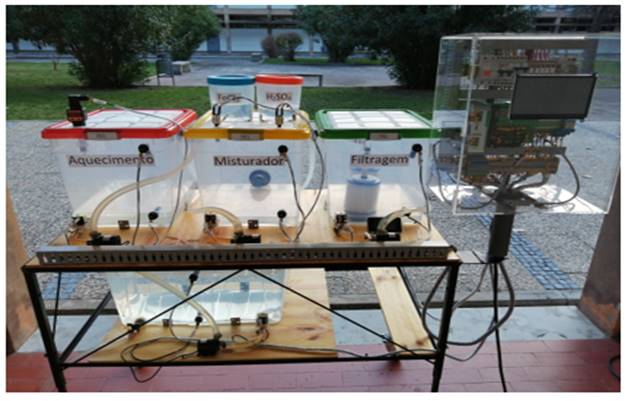
Water and wastewater treatment plants are essential to provide drinking water the humans and animals and to reuse water in agriculture, gardens, fountains, washing vehicles, among other applications. Teaching and understanding the operation of water treatment plants is essential to engineers who perform operations in such places Jaiad and Ghayyib (2017) The didactic simulator presented is made with six containers of three different sizes for water storage, interconnected by the respective pipes. The largest container serves as a reservoir while in the remaining three are simulated different stages of a water and wastewater treatment plant: heating, mixing, and filtering. The solution is based on a two-story structure designed with high portability to be moved to different locations. To approximate the developed didactic simulator to the basic functioning of a water/wastewater treatment plant, several sensors and actuators with real action were used: four centrifugal electric pumps with brushless DC motors, six normally closed plastic solenoid valves, eight float level sensors, two temperature sensors, an 850W heating resistor, a 150W mixing pump and two manual valves to purge the system. To control the simulator was used the ILC 131 ETH PLC from Phoenix Contact. It has 8 digital inputs and 4 outputs, together with 5 expansion modules: an IB IL 24 DI8 HD/PAC module with 8 binary inputs; an IB IL 24 DO8 HD/PAC module with 8 binary outputs; an IB IL 24 DO4/ME module with 4 binary outputs; an IB IL AI2 SF/ME module with 2 analog inputs (voltage or current selectable) and an IB IL RS232/ECO module for serial communication over RS232-C. The PLC is connected to a Raspberry Pi 3 with a touch panel display that provides supervision and the respective Human-Machine Interface (HMI). An android application was also developed to communicate via Bluetooth with the Raspberry Pi to add some possibility of configuration and remote monitoring of the simulator's status. The Raspberry Pi is a well-known compact and low-cost computer able to perform numerous functions Pawar and Latane (2018) Apart from the sensors and actuators, all equipment, as well as the electrical connections and respective protections are stored in an electrical panel. For didactic purposes, its construction is in acrylic so students and others can view its interior. The panel also has an on/off switch with LED to turn the simulator on and off and its power supply is provided by the low voltage network, with protection through a 25A differential switch. The simulator is represented in Figure 1
Figure 1
|
Figure 1 Didactic Simulator |
3.2. DESCRIPTION OF SIMULATOR COMMUNICATION
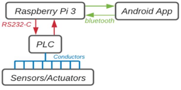
To fulfil the proposed objectives, it was necessary to design a communication network that would interconnect the sensors/actuators, the PLC, the Raspberry Pi, and the mobile phone with the android application.
The connection of sensors (binary or analog) and actuators is done directly (or through relays) with conductors to the physical inputs of the PLC through the terminals provided for this purpose.
Given the simplicity of the solution, an RS232-C point-to-point serial communication network with simplex transmission was established to interconnect the PLC and the Raspberry Pi. Bluetooth wireless communication was also used to connect the Raspberry Pi to the mobile phone with an android application developed specifically for this simulator. This choice was made based on the architecture and intended objectives for the simulator. Because it’s a local access point-to-point communication with short distances between equipment’s Palma (2004) for demonstration purposes with a low level of risk regarding security, both communication solutions (both RS232-C and Bluetooth) are reliable and has moderate difficulty on implementation. Figure 2 illustrates a simple schematic for the device connections.
Figure 2
|
Figure 2 Schematic of the simulator communication |
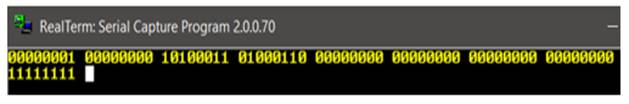
To interpret the data that is being sent or received, it was necessary to define the body of the message. It's composed of 9 bytes (8 data and 1 auxiliary), that contains the states of all sensors, actuators and supervision variables, some auxiliary bits, and a list of errors. Figure 3 shows an example of a message sent from the PLC to the Raspberry Pi using RS232-C serial communication.
Figure 3
|
Figure 3 Example of a RS232-C message |
Reading from left to right, in byte 1 are some auxiliary bits and a list of errors, in bytes 2 and 3 is the actual measured temperature value, in bytes 4 to 6 are the states of sensors and actuators Table 1 and in bytes 7 and 8 is the reference value for temperature. Byte 9 is an end-of-message auxiliary byte with its bits always set to “1”, to perform a basic error checking on the Raspberry Pi side.
Table 1
|
Table 1 Description of part of the RS232-C message |
||
|
Byte |
Bit |
Sensor/Actuator |
|
4 |
1 |
Simulator
on/off switch |
|
2 |
Reservoir
high level sensor |
|
|
3 |
Tank
1 high level sensor |
|
|
4 |
Tank
2 high level sensor |
|
|
5 |
Tank
3 high level sensor |
|
|
6 |
Reservoir
low level sensor |
|
|
7 |
Tank
1 low level sensor |
|
|
8 |
Tank
2 low level sensor |
|
|
5 |
1 |
Tank
3 low level sensor |
|
2 |
Virtual
on/off switch (supervision) |
|
|
3 |
Virtual
manual/automatic mode selector (supervision) |
|
|
4 |
Auxiliary
bit |
|
|
5 |
Reservoir
solenoid valve |
|
|
6 |
Tank
1 solenoid valve |
|
|
7 |
Tank
2 solenoid valve |
|
|
8 |
Tank
3 solenoid valve |
|
|
6 |
1 |
Tank
2 reagent solenoid valve (left) |
|
2 |
Tank
2 reagent solenoid valve (right) |
|
|
3 |
Reservoir
electric pump |
|
|
4 |
Tank
1 electric pump |
|
|
5 |
Tank
2 electric pump |
|
|
6 |
Tank
3 electric pump |
|
|
7 |
Heating
resistor |
|
|
8 |
Mixing
pump |
|
For the Bluetooth communication, the body of messages sent between the android application and the Raspberry Pi was changed, simplifying them. This change was made because it's possible to send messages in text format with UTF-8 encoding and due to the type of programming used in the development of the android application. In the message Raspberry Pi -> android app, the values of each variable were converted to decimal, except for the 24 bits related to the inputs/outputs that kept their binary representation according to Table 1 sent with the format ##Errors, Temperature, Ref Temperature, Filling Times, 24bitFF. Where ## and FF represent the beginning and end of the message and the variables are divided by commas. In the case of the message android app -> Raspberry Pi, it is simpler and more effective to send the command relative to the state of the device to be changed, instead of always sending the complete message with all the states of all the devices. As such, the body of the message to be sent is ##XXX00000000FF, where XXX identifies the equipment and 00000000 its states or value. The devices are described in Table 2 and the possible states are 00000000 and 00000001 for off and on, respectively. As for the temperature values, three digits were used to represent them with one decimal place, filling the remaining ones with "0" (ex.: 00000344 = 34.4ºC). In the tank filling times, in both messages, each digit represents a multiplicative factor (0-0sec; 1-5sec; 2-10sec; 3-15sec; 4-20sec; 5-25sec; 6-30sec), with the order of intermediate time and final time of the three tanks, time for tank 4 and time for tank 5.
Table 2
|
Table 2 Description of the android application-Raspberry Pi message |
|||
|
Equipment |
App
Message (XXX) |
Equipment2 |
App
Message (XXX) |
|
On/off
switch |
STR |
Reservoir
electric pump |
EBR |
|
Mode
switch (manual/auto) |
MOD |
Tank
1 electric pump |
EB1 |
|
Reservoir
solenoid valve |
EVR |
Tank
2 electric pump |
EB2 |
|
Tank
1 solenoid valve |
EV1 |
Tank
3 electric pump |
EB3 |
|
Tank
2 solenoid valve |
EV2 |
Heating
resistor |
RES |
|
Tank
3 solenoid valve |
EV3 |
Mixing
pump |
MIS |
|
Tank
2 reagent solenoid valve (left) |
EV4 |
Temperature
reference value |
TMP |
|
Tank
2 reagent solenoid valve (right) |
EV5 |
Tanks
filling times |
TIM |
3.3. DESCRIPTION OF THE SIMULATED PROCESS
Because of the didactic component of the simulator, a visual, practical, and intuitive solution related to the theme of water treatment plants was designed. The process consists of a flow cycle of the existing water in the system through the four tanks, starting in the reservoir and simulating three stages: heating, mixing, and filtering. Before starting, all the water of the system must be in the reservoir, filling it manually to the maximum level to ensure that it's sufficient to fill the tanks of the following stages. It was planned to have two switches to start and stop the system, with interlocking safety: a physical one present on the electrical panel door and a virtual one on the supervision program. Once started, the simulator allows two modes of process operation - manual and automatic - with the manual command orders made through the supervision existing on the Raspberry Pi and/or in parallel by the android application.
In automatic mode, the pumping process is done sequentially and cyclically, running all the tanks, and returning to the reservoir, repeating while all conditions are true.
In manual mode, the user is allowed to manipulate all the electric valves and pumps, changing the levels of the tanks freely. This adds a layer of difficulty when switching from manual to automatic mode because of the uncertainty of tank levels after each use in manual mode. Therefore, it was necessary to create an initialization algorithm that allows the PLC to guarantee that the initial conditions are met and that there is enough water to complete the cycle in automatic mode. With the manual control of the process by the user, after handling the electric valves and pumps, there are several scenarios possible for the distribution of water. The initialization algorithm must be able to reset the initial conditions so that the cyclic operation in automatic mode can work properly. It starts by ensuring that the reservoir has the desired water level. Then checks the status of the tank sensors. To include all possible scenarios, two checks are carried out: if at least one of the three tanks does not have water (i.e., low level sensors = 0) or if the three tanks have water (i.e., low level sensors = 1).
3.4. IMPLEMENTATIONS IN THE ILC 131 ETH PLC
The ILC 131 ETH PLC is the equipment where all the instructions and tasks described are carried out, as well as the safety operations.
The PLC programming was developed in PCWORX software using four of the five languages of the IEC 61131-3 standard: function block diagram, ladder diagram, sequential function chart and structured text. It's divided into seven programs, implementing the initialization algorithm, automatic mode, manual mode (among others), error list, analog input handling and serial communication. Because it's sequential behaviour, the initialization algorithm and the automatic mode programs were developed with sequential function chart language. The manual mode and treatment of the analog input were developed in function block and ladder diagrams and the error list with structured text language. For serial communication, two programs were developed: one with function block diagram to configure the RS232 module and another in structured text language to define the communication mode. All programs are running in the PLC's internal cycle, except for the analog input handling, which runs in a separate cycle, every 100ms.
3.4.1. Initialization Algorithm
The initialization algorithm program was developed with sequential function chart, using function block and ladder diagrams for its transitions and actions, taking advantage of some of the programming characteristics of PCWORX. Two auxiliary variables were created – Cycle_Init and Cycle Auto – to control the program status. The variable Cycle_Init indicates if the program has already performed the initialization algorithm, changing its state to "1" when it does. In the case of the Cycle Auto variable, it changes its state to “1” when the program can start in automatic mode.
Before the system starts and after pumping water from the reservoir to tank 1, it's carried out a check on the reservoir water levels. If the reservoir is empty, an alarm is activated, and the program returns to the initial stage. If there is water, the program continues pumping water sequentially between tanks, filling and emptying them until the water is below the minimum level (low sensor = 0) on all of them. At the end, the variables Cycle_Init and Cycle Auto are set, indicating that the initialization algorithm has been performed and that the program is ready to start in automatic mode.
In the situation where the three tanks have the minimum level (low sensor = 1), the water is pumped between the tanks simultaneously until they lose their minimum level. If the initial conditions are true, the sequential function chart enters an AND branch, executing the steps simultaneously until the output conditions are reached. In each action, the water is pumped to the next tank, activating the respective electric valve and pump, conditioned by the state of the low-level sensors. The sequential function chart exits the AND branch when all tanks lose their low-level signal given by the sensor, doing a set to the variables Cycle_Init and Cycle Auto and ending the initialization algorithm. Its block diagram is described in Figure 4
Figure 4
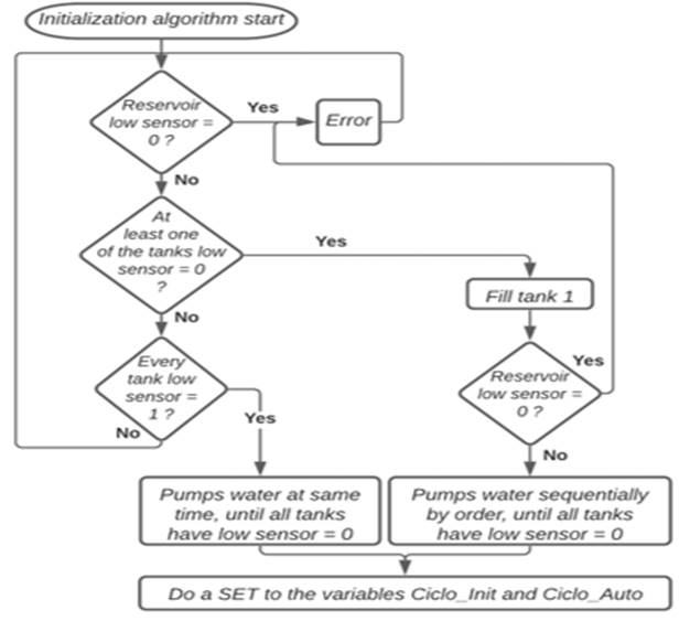
|
Figure 4 Block diagram of the initialization algorithm |
3.4.2. Automatic Mode
Once the initialization algorithm is finished, the program can start in automatic mode, if there is water in the reservoir, has a start indication (physically and by supervision) and has the selector in automatic mode. When the automatic mode is started, all actions are carried out sequentially if the respective transitions allow it. The start indication (physically and by supervision) and the selector in automatic mode must always be present or the program stops.
The program starts by filling up tank 1 halfway and power on the heating resistor, waiting then for the water to heat up until it reaches the set point. While the value is reached, tank 1 is filled to the maximum level if it's not yet full. With tank 1 full or the reservoir empty, it begins to fill half of tank 2 and the reagents solenoid valves are switched on in turns. After that the mixing pump is powered on for 30sec and tank 2 is filled to the maximum level. With tank 2 full, the water is pumped to tank 3, stopping when it is full or when tank 2 is empty. With tank 3 full, the system waits 10 seconds before pumping water back into the reservoir. The program can repeat its cycle if the initial conditions are true. Its block diagram is described in Figure 5
Figure 5
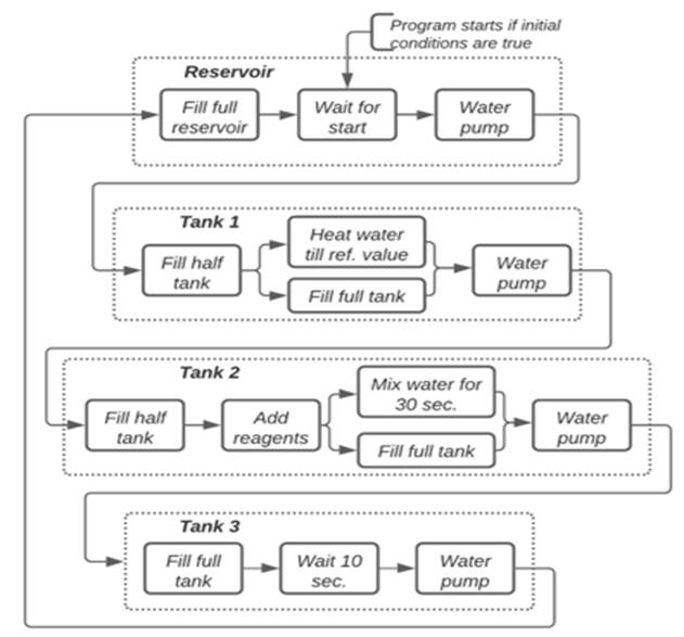
|
Figure 5 Program block diagram |
3.4.3. Manual Mode
The manual mode was programed in the main program as well as the assignment of the PLC's internal inputs/outputs and safety interlocks, among others. The main program was developed in ladder diagram using, sometimes, function block diagrams.
Once the simulator is powered up and started, the PLC and Raspberry Pi are powered on. To ensure that the interface on the Raspberry Pi starts before the PLC program, a 20 second delay has been implemented in the program. During the delay time, the LED of the on/off switch will flash intermittently each second, to inform the user. At the end of the delay time, the LED turns off, lighting up only when the switch is activated.
To ensure that the simulator starts the initialization algorithm when it returns to automatic mode, a reset is made to the Cycle_Init and Cycle Auto variables whenever the state of any electric pump or valve is changed. However, if the simulator enters manual mode, but no actuator is used, the simulator is not obliged to perform the algorithm, to optimize it. A safety interlock is also carried out, in the case of electric pumps, so that they only work with the respective valve active.
At any time, the program must stop when it loses the on/off switch state. This stop must happen even in an extreme situation like interface blocking or loss of communication. For that, the switch state is present as a condition in all transitions and program actions. All actuators in the system are reset when the order to stop is received (switch off).
3.4.4. List of errors and warnings
To list the errors and warnings of the didactic simulator, a program was created using structured text language. Depending on the conditions that trigger the error/warning, an integer (maximum 63) is written in a byte-type variable that is then sent to the Raspberry Pi to be interpreted and represented in the interface. The list Table 3 is dynamic and can be changed on the PLC and on the Raspberry Pi whenever necessary.
Table 3
|
Table 3 List of errors and warnings description |
|
|
Decimal
digit |
Error/warning |
|
0 |
(Empty
field, no error message) |
|
1 |
Program
stopped |
|
2 |
Program
in manual mode |
|
3 |
Program
in automatic mode |
|
4 |
Empty
reservoir |
|
5 |
Reservoir
sensors malfunction |
|
6 |
Faulty
sensors in tank 1 |
|
7 |
Faulty
sensors in tank 2 |
|
8 |
Faulty
sensors in tank 3 |
3.4.5. Serial Communication
Serial communication was performed with a baud rate of 9600 bits/s, 8 data bits, even parity and 1 stop bit. It starts by sending the 9-byte message and then receiving it with a timeout of one second. Both sending and receiving are performed by checking the status of the respective buffers (if they are full, empty and if there is data). Communication ends after the message is received or by reaching the timeout time. The message is then divided and assigned to the global variables of the PLC. The measured and reference temperature values are also processed in the serial communication PLC program.
3.5. IMPLEMENTATIONS IN THE RASPBERRY PI
On the Raspberry Pi was used ERIC software to develop the graphical supervision interface of the didactic simulator. Four python classes were created: two for the graphical representation of the didactic simulator and another two, running in the background, for the communication with the PLC and the android application. Variable sharing between different classes is performed using slots and signals, a tool used by PyQt that allows the creation of flags. To create a signal the expression signal=pyqtSignal (variable type) is needed at the beginning of the class and then the expression signal. Connect (slot) to assign it to a slot.
3.5.1. Graphical Supervision Interface
The interface is divided in three windows: The first presents the name of the project and the ISEL logo. On the second window, the user confirms whether there is water in the reservoir, serving as a requirement to advance to the third window. If this condition is not met, an error message is displayed. In the third window, the process is presented, subdivided into tabs. In all windows there is a button that allows the user to exit the interface.
The third window or process window Figure 6 it's subdivided into five separators – general, heating, mixing, filtering, manual – representing the process in different operating modes. In all of them it's possible to access the process start/stop switch and the operating mode selector. The general tab shows a global representation of the process. All tanks and their respective valves, pumps and water levels are shown. The measured temperature value and the states of the heating resistor and mixing pump are also displayed.
Figure 6
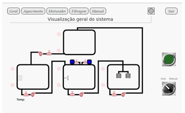
|
Figure 6 Process window (general tab) |
In the upper right corner, there’s also a settings icon that gives access to a history of events or logs and some information about the interface.
3.5.2. Supervision interface functionality
The development of the interface functionality is divided into two python classes: Main Window and Process Window. In the Main Window class, the first two presentation windows were developed while the process representation window was developed in the Process Window class. Both classes were created taking advantage of the stacked widget that allows the creation of several windows in a single element. In this way, it is possible to include several windows in a single space, reducing and optimizing their functional code in python. During the interaction between the user and the interface, several buttons will be selected that will perform different functions. When a button is selected, it triggers a function created in the respective class. Once the interface is initialized, the code for the Main Window class runs. In its code, the communication threads are configured and started, and slots are assigned to the created signals. When the third window (process) is opened, the code of the Process Window class runs. This class oversees processing the data received from the PLC and updating the graphical representation of the process in the interface, so it's in constant contact with the serial communication thread.
3.5.3. Communication with PLC and android application
For the development of the communication platform, two object-type classes were created in python: Serial Thread and Bluetooth Thread. One of the main restrains was the Raspberry Pi's ability to respond to user interaction with the interface and process communication requests with the PLC and the android application at the same time. To overcome this difficulty, the concept of thread was used in the implementation of the classes.
Both threads have a similar operation, differing only in their implementation. They start by opening a socket or port to establish their communication, then wait for the data to send or receive. Because both the interface and the application work in parallel, acting as the supervision, the data flow was centralized in the Serial Thread to be sent to the PLC. Its block diagram can be analysed in Figure 7
Figure 7
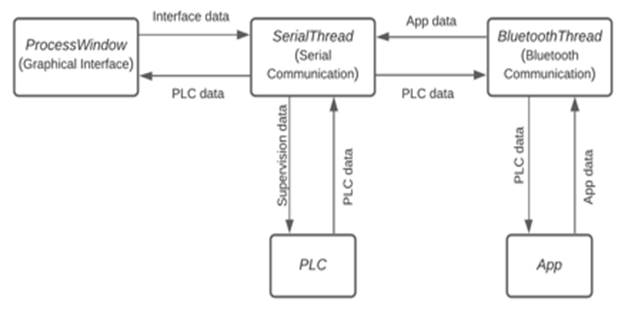
|
Figure 7 Data flow block diagram |
3.6. IMPLEMENTATIONS IN THE ANDROID APPLICATION
The android application was developed using the MIT App Inventor online platform developed by the Massachusetts Institute of Technology (MIT). For the development of the application, 5 windows were designed, each one with its own functionality: Initial Window; Menu; Manual Mode; Synoptic; Settings. Some layouts of the Android application can be seen in Figure 8
Figure 8
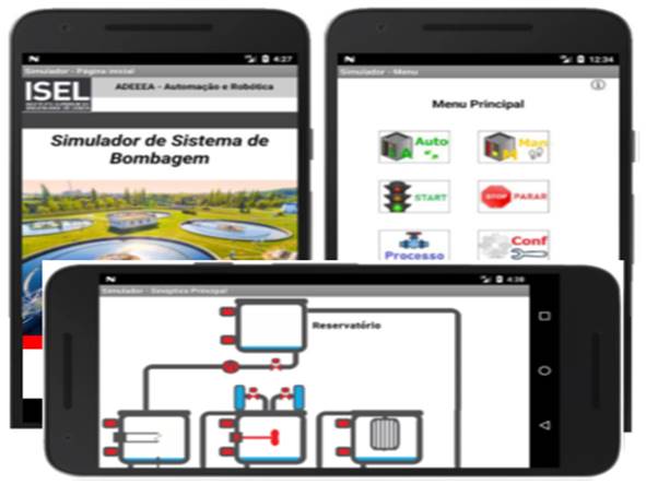
|
Figure 8 Android application developed in the MIT app |
When the initial window is initialized, the Bluetooth connectivity is checked, showing the list of previously paired devices, allowing the user to choose the device to which he wants to connect. Once the Bluetooth connection is made, the name and address of the device are stored so that, when the application is started again, it’s not necessary to repeat the process. If the connection is successful, a success message is displayed on the screen. If not, an error message is displayed. Due to a limitation imposed by the MIT App Inventor online platform, it’s not possible to keep the Bluetooth connection active between windows and, therefore, this check is carried out whenever a window is started or manually by the user through a button visible in each window. Once the verification is finished, the application waits for the user to interact with the buttons or selectors in it.
4. CONCLUSION
With the didactic simulator developed, it was possible to study and apply the different areas of industrial automation such as instrumentation, control, power, networks, and communication protocols. It was also possible to use some recent technology such as the Raspberry Pi and the android system and integrate them with the most used equipment in the industrial environment: the PLC.
Due to the complexity of the project, throughout its development several challenges appeared. Many were already expected, but some emerged unexpectedly, forcing an adaptation of the project. One of the challenges was related to the equipment used. Because they were new, it was necessary to study and familiarize with the operation of Phoenix Contact PLC, Raspberry Pi, and android system. However, the biggest challenge was to integrate the communication between the three devices in a high-level programming language like python, keeping the graphical supervisory interface functional and intuitive. To achieve it, there was a significant learning curve from creating simple examples that sends and receives small messages between the PLC, the Raspberry Pi, and the android application, to the final interface where data is exchanged in real time. With this type of communication, the adoption of a structure using communication threads was essential to keep the graphical interface of supervision functional and intuitive. In the course of the work, an improvement in the simulator was also considered, consisting in an interactive solution based on the filling times for each tank. However, it was not implemented in its entirety, being suggested as a future work. The simulator program was developed as flexible and intuitive as possible, so it could be changed in the future by colleagues or students through the normal programming of the PLC and the parameters of the messages body already described.
As it is a practical work, the fundamental experimental result to be taken from the developed solution is the good functioning of the didactic simulator. The simulator will be used in department presentations at ISEL (Instituto Superior de Engen aria de Lisboa, or Lisbon Engineering School).
In general, the didactic simulator presented in this paper fulfils the proposed objectives, being functional to be used by ISEL students. It is possible to heat, mix and filter the water automatically and manually through a touch screen display and an android application installed on the mobile phone. All sensors and actuators states are shown in real time in the supervision, as well as some error and diagnostic messages.
CONFLICT OF INTERESTS
None.
ACKNOWLEDGMENTS
None.
REFERENCES
Chaos, D. Chacón, J. Lopez-Orozco, J. A. Dormido, S. (2013). Virtual and Remote Robotic Laboratory Using EJS, MATLAB and LabVIEW. 13, 2595-2612. https://doi.org/10.3390/s130202595
Jaiad, A. T. & Ghayyib, H. S. (2017). Controlling and monitoring of automation water supply system based on iot with theft identification. International Journal of Research -GRANTHAALAYAH, 5(5), 320-325. https://doi.org/10.29121/granthaalayah.v5.i5.2017.1863
Lima, N. et al. (2017). Do Students Really Understand the Difference Between Simulation and Remote Labs ? https://doi.org/10.1145/3144826.3145362
Ma, J. Nickerson, J. V. (2006). Hands-on, simulated, and remote laboratories: A comparative literature review Hands-On, Simulated, and Remote Laboratories: A Comparative Literature Review, no. ACM Computing Surveys, 38(3). https://doi.org/10.1145/1132960.1132961
Naumovic, M. & Zivanovic, D. (2008). Remote Experiments in Control Engineering Education Laboratory. iJOE. 48-53.
Palma, J. (2004). Introdução to fieldbuses in Automation (Portuguese document).
Pawar, K. & Latane, P. (2018). Internet of things (iot) based advanced online examination using raspberry pi. International Journal of Research -GRANTHAALAYAH, 6(5), 30-36. https://doi.org/10.29121/granthaalayah.v6.i5.2018.1417
Pereira, C. E. Paladini, S. and Schaf, F. M. (2012). Control and automation engineering education : Combining physical, remote and virtual labs, International Multi-Conference on Systems, Signals & Devices, 1-10. https://doi.org/10.1109/SSD.2012.6197908
Shuman, L. J. et al. (2002). The future of engineering education, 32nd ASEE/IEEE Frontiers in Education Conference, November, 6-9.
Wulf, W. A. and Fisher, G. M. C. (2002). A makeover for engineering education, Issues Sci. Technol, 18(3), 35.
 This work is licensed under a: Creative Commons Attribution 4.0 International License
© Granthaalayah 2014-2022. All Rights Reserved.