Computational Analysis of Butterworth and Chebyshev-I Filters using Bilinear Transformation
A. Muhammad 1, S.K. Singh 1![]() , I. Umaru 2, M.M.
Usman 1, M.N. Abdulkareem 1, M.I.
Abubakar 1, M.S Nur 1
, I. Umaru 2, M.M.
Usman 1, M.N. Abdulkareem 1, M.I.
Abubakar 1, M.S Nur 1
1 Federal University of Kashere, Department of Physics, Akko, Nigeria
2 Nasarawa State University, Department of Physics, Keffi, Nigeria
|
|
|
ABSTRACT |
|
|
Due to the
intense demands in advanced telecommunications during the last fifteen years
for both higher spectrum band and better accuracy, the digital Infinite
Impulse Response (IIR) filter has emerged as the basic component in both
digital telecommunication and Digital Signal Processing (DSP) systems. In our
research work reported in this paper we conducted meticulous investigation
using computer simulation of the digital Infinite Impulse Response (IIR)
filter to implement the Butterworth and Chebyshev I procedure with bilinear
transformation algorithm aimed at both statistical analysis and computer
simulation. Our simulation results reveal the comparative accuracy between
digital filters and analog filters of the spectrum response in i) absolute
magnitude, ii) the magnitude in decibels (dB) and iii) phase. Conversely the
filter selectivity and gain in decibel scale were numerically obtained. |
|||
|
Received 02 May 2022 Accepted 05 June 2022 Published 30 June 2022 Corresponding Author S.K.
Singh, DOI 10.29121/granthaalayah.v10.i6.2022.4571 Funding: This research
received no specific grant from any funding agency in the public, commercial,
or not-for-profit sectors. Copyright: © 2022 The
Author(s). This work is licensed under a Creative Commons
Attribution 4.0 International License. With the
license CC-BY, authors retain the copyright, allowing anyone to download,
reuse, re-print, modify, distribute, and/or copy their contribution. The work
must be properly attributed to its author.
|
|||
|
Keywords: Butterworth Analogue and Digital Filters,
Chebyshev I Analogue and Digital Filters, Infinite Impulse Response (IIR)
Filter, Filter Selectivity, Bilinear Transformation (BLT) |
|||
1. INTRODUCTION
Digital signal processing (DSP) experienced phenomenal advances in both research and application in the past few decades due to progresses in digital computer technology and software development. Digital filter is one of the most important and frequently used elements of DSP. It is a frequency selective device which extract the useful part of the input signal within its operating frequency range Mitra (2001) Aggarwal et al. (2015) Infinite impulse response (IIR) -recursive and Finite impulse response (FIR) -non -recursive are the two broad classes of digital filters. IIR tends to be ideal at lower filter order (less number of coefficients) make it preferable to FIR. Conversely, non-recursive algorithm of FIR filter has greater filter order as compared to IIR filter.
However, diverse methods exist for the design of digital filters. Mostly, five methods are used to design IIR digital filters viz: Bilinear transformation method, Impulse-invariance method, Backward difference method, Step-invariance methods, and Matched-z-transformation Madisetti and Williams (1999) Bilinear transformation method is used in this research for its simplicity and similarity to analogue filter.
The design of IIR digital filters with Butterworth and Chebyshev I filter responses, using MATLAB software are based on the concepts of bilinear transformation and analog filters. So, they are universally used to approximate the piecewise constant magnitude characteristic of ideal LP, HP, BP, and BS filters Kou et al. (2006)
A desired design of
IIR filter can be achieved with the support of specifications: the passband
frequency ![]() ,
stopband frequency
,
stopband frequency ![]() ,
maximum allowable passband ripple
,
maximum allowable passband ripple ![]() ,
minimum allowable stopband ripple
,
minimum allowable stopband ripple ![]() and bandwidth
and bandwidth ![]() .
.
However, the design of IIR filters is more difficult than FIR filters design for their rational transfer functions. Moreover, it is necessary to consider the stability of the filters and linear phase design may be achievable Saini and Kaur (2015)
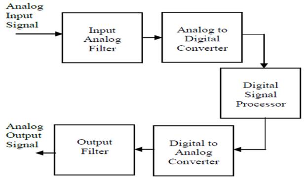
The necessary algorithm use in converting Analogue to digital filter is given Natarajan (2017)
Figure 1
|
Figure 1 Block diagram of digital signal processing system |
2. METHODOLOGY
The Bilinear Transform method applied in designing frequency selective filters yields very efficient results as to other mapping methods listed above for designing IIR digital filters. Digital filters resulting from the bilinear transform will preserve the magnitude response characteristics of the analog filters, at the expense of the time domain properties. This method is better for designing frequency selective IIR digital filters.
This method credited simplicity and similarity of frequency response of IIR digital filters to that prototype analog filter. The bilinear transform requires higher sampling frequency which in turn requires lower sampling rate. It overcomes effects of aliasing that is caused due to analog frequency response containing components at or beyond the half sampling (Nyquist) frequency somewhat degraded by frequency warping. This method is the result of one-to-one mapping from s-plane to z-plane inherent. In addition, the filter roll-off characteristics are sharper using this method.
Furthermore, the Bilinear Transform of analog prototype filter has less limitations and exists in: lowpass, high pass, bandpass and band stop filters.
This design starts with the transfer function of an analog filter, and then a mapping from s (Analog) to z (Digital) plane results in a general form for an IIR filter with an arbitrary number of poles and zeros Verma (2013)
A digital filter can be characterized as a linear time invariant (LTI) discrete system by a constant coefficient difference equation Proakis and Monalakis (2002), Shenoi (2006)
where a(k) and b(k) are the forward tap coefficients and feedback tap coefficients respectively.
The frequency domain response function can be obtained from its z-transform Balami et al. (2020) Islam and Aktar (2019) Jamal et al. (1996)
![]()
![]() Equation 2
Equation 2
![]() Equation 3
Equation 3
The mapping or transformation that relates points on the s-plane to z-planes is defined as Kou and Lee (2001), Shenoi (2006)
![]() Equation 4
Equation 4
where T is the indicated sample period
Therefore, the digital transfer function can be calculated in terms discrete time variable z as follows Patanavijit (2020)
The mapping between the continuous-time spectrum (-∞≤Ω≤∞) to the discrete-time spectrum (-π≤ω≤π) can be computed as:
![]() Equation
6
Equation
6
where Ω is the analog frequency and ω is the digital frequency
![]() Equation 7
Equation 7
This is a non-linear relation, and it is known as prewarping
Theoretical Design Parameters
![]() :
maximum variation
:
maximum variation
![]() :
minimum stopband attenuation
:
minimum stopband attenuation
![]() :
passband ripple in decibel (dB)
:
passband ripple in decibel (dB)
![]() :
stopband ripple in decibel (dB)
:
stopband ripple in decibel (dB)
![]() :
passband frequency in (Hz)
:
passband frequency in (Hz)
![]() :
stopband frequency in (Hz)
:
stopband frequency in (Hz)
![]() :
sampling frequency in (Hz)
:
sampling frequency in (Hz)
![]() :
sampling rate in (Hz)
:
sampling rate in (Hz)
![]() :
digital passband frequency in (rad)
:
digital passband frequency in (rad)
![]() :
digital stopband frequency in (rad)
:
digital stopband frequency in (rad)
![]() :
analogue passband frequency in (rad/sec)
:
analogue passband frequency in (rad/sec)
![]() :
analogue stopband frequency in (rad/sec)
:
analogue stopband frequency in (rad/sec)
![]() :
ripple parameter
:
ripple parameter
![]() :
a constant
:
a constant
![]() :
region of convergence (ROC) of the poles and zeros
:
region of convergence (ROC) of the poles and zeros
![]() :
Filter Selectivity
:
Filter Selectivity
Theoretical Design Equations
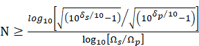
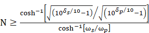
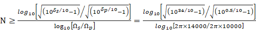
The filter order (N) Butterworth filter can be obtained by:
The filter order (N) Chebyshev I filter can be computed by:
The analogue angular frequency in the passband
![]() Equation 10
Equation 10
The analogue angular frequency in the stopband
![]() Equation
11
Equation
11
![]() Equation 12
Equation 12
![]() Equation 13
Equation 13
The digital passband cut-off frequency ![]()
The digital stopband cut-off frequency ![]()
The cut-off frequency can be anywhere in the interval
![]() Equation
16
Equation
16
The digital frequency is related to analogue frequency in passband and stopband respectively by the relations Scarpa (2013) Ramesh et al. (2009)
![]() Equation 17
Equation 17
![]() Equation 18
Equation 18
The modified prewarping frequency in the passband and stopband can be computed by equations Equation 19 and Equation 20 respectively as:
The pole position of Butterworth filter can be computed by Abu-hudrouss (2009)
![]() Equation
21
Equation
21
Where
The region of convergence ![]() of the poles and zeros is determined as Abu-hudrouss
(2009)
of the poles and zeros is determined as Abu-hudrouss
(2009)
![]() Equation
24
Equation
24
The poles of Chebyshev I filter can be analysed by the relation:
Where ![]() is
given by equation Equation 23
is
given by equation Equation 23
The minor ![]() axis of the pole can be obtained by the
relation:
axis of the pole can be obtained by the
relation:
The major ![]() axis
of the pole can be computed by the relation:
axis
of the pole can be computed by the relation:
![]() Equation 30
Equation 30
The transfer function of the filter can be found by the relation Aremu et al. (2013), Prêle et al. (2021), Aremu et al. (2013)
Where
![]() Equation
34
Equation
34
Design specifications
![]()
![]()
![]()
![]()
![]()
Calculations of Design specifications
![]()
![]()
![]()
![]()
![]()
![]()
![]()
![]()
Calculation of Design Parameters Using Bilinear
Transformation (BLT)
Ripple Parameters
![]()
![]()
Prewarping the frequency
![]()
![]()
![]()
Table1
|
Table 1 Comparison of Butterworth and Chebyshev I Lowpass Filters |
||||||||
|
Filter
Type |
Response
Type |
Filter
Order |
Filter
Selectivity |
Region
of Convergence (ROC) |
Transition
Frequency (KHz) |
|||
|
Analogue |
Digital |
|||||||
|
Passband |
Stopband |
Passband |
Stopband |
|||||
|
Butterworth |
Lowpass |
15 |
4.7309 |
0.9391 |
29 |
|
31.5 |
|
|
Chebyshev
I |
Lowpass |
7 |
2.2078 |
0.8741 |
36.25 |
|
36.25 |
|
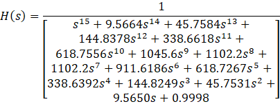
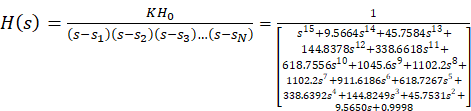
The denominator of the analogue transfer function ![]() of the normalized 15th order Butterworth
filter as depicted in Table 2 is obtained using
quadratic polynomial equation Equation 35
of the normalized 15th order Butterworth
filter as depicted in Table 2 is obtained using
quadratic polynomial equation Equation 35
Table 2
|
Table 2 Butterworth polynomial quadratic factors for filter order (N=15) |
|
|
N |
|
|
0 |
1 |
|
1 |
|
|
2 |
|
|
3 |
|
|
4 |
|
|
5 |
|
|
6 |
|
|
7 |
|
|
8 |
|
|
9 |
|
|
10 |
|
|
11 |
|
|
12 |
|
|
13 |
|
|
14 |
|
|
15 |
|
![]() Equation
37
Equation
37
![]() Equation
38
Equation
38
Table 3
|
Table 3 Digital Transfer Functions Calculated Using BLT Algorithm |
|
|
Designed
Filter |
Transfer
Function |
|
Butterworth |
|
|
Chebyshev
I |
|
Table 4
|
Table 4 Digital Transfer Functions Calculated Using Z-Transform |
|
|
Designed
Filter |
Transfer
Function |
|
Butterworth |
|
|
Chebyshev
I |
|
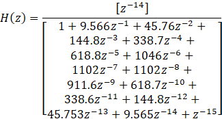
Design Procedures of Butterworth Filter
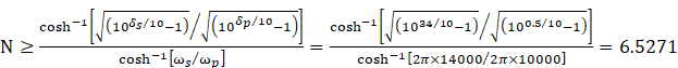
1) Determine the filter order (N) using equation Equation 8
![]()
![]()
2) Determine
the cut-off frequency ![]() from the expressions of constraints using Equation 14 and Equation 15
from the expressions of constraints using Equation 14 and Equation 15
![]()
![]()
![]()
3) For the computed N determine the denominator polynomial of normalized H(s) from the Table 2 which was computed using equation B_N i.e., Equation 36 which is computed using equation Equation 22
4) The numerator of the transfer function is obtained using equation (33).
![]()
Since ![]() odd
odd
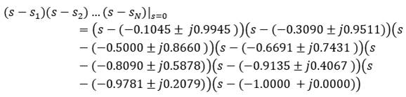 .
.
Setting (s=0)
![]()
![]()
![]() is
is ![]()
![]()
5) The transfer function can be obtained using equation (30), (31) and (32) as:
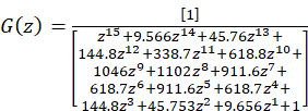
The digital transfer function is calculated using equation (5) (Patanavijit, 2020):
![]()
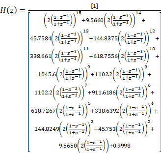
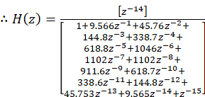
The analytical solution of digital transfer function using z- transform is given as:
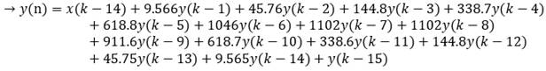
The difference equation of the digital transfer function can be computed using equation Equation 1 as:
![]()
6) Adjust the gain of the filter by the desired amplification factor, if needed.
The dc gain of the filter: ![]() The
dc gain: which gives |G (1)|=1
The
dc gain: which gives |G (1)|=1
![]()
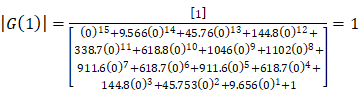
![]()
![]()
Thus,
G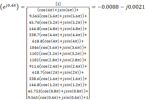
![]()
![]()
The filter Selectivity of lowpass Butterworth filter is obtained using equation (35)
![]()
The region of convergence ![]() of Butterworth lowpass filter can be obtained using
equation (24)
of Butterworth lowpass filter can be obtained using
equation (24)
![]()
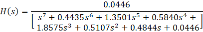
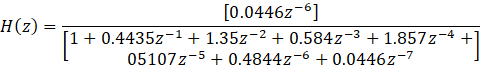
Design Procedures of Chebyshev I Filter
1) Determine the filter equation (N) using equation Equation 9
![]()
![]()
2) Determine
![]() from
the expressions of constraints using Equation 14 and Equation 15 For the computed N
determine the denominator (pole) polynomial of normalized H(s) The normalized
denominator (pole) polynomial of the transfer function is obtained using Equation 23 Equation 25 Equation 26 Equation 27 Equation 28 and Equation 29
from
the expressions of constraints using Equation 14 and Equation 15 For the computed N
determine the denominator (pole) polynomial of normalized H(s) The normalized
denominator (pole) polynomial of the transfer function is obtained using Equation 23 Equation 25 Equation 26 Equation 27 Equation 28 and Equation 29
![]()
![]()
The minor axis ![]() is computed as:
is computed as:
![]()
The major axis ![]() is calculated by:
is calculated by:
![]()
![]()
![]()
![]()
![]()
The denominator (pole) of the transfer function using denominator of Equation 31
![]()
![]()
![]()
![]()
![]()
Thus, the denominator of the transfer function is:
![]()
Since ![]() is odd the numerator of the transfer function
in Equation 31 can be obtained using Equation 33
is odd the numerator of the transfer function
in Equation 31 can be obtained using Equation 33
![]()

![]()
The transfer function of the filter can be evaluated using Equation 33 Equation 32 Equation 31
![]()
![]()
The analytical solution of digital transfer function using z- transform is obtained using Equation 5
![]()
H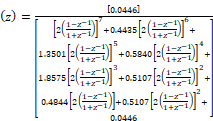
![]()
· The dc gain of the filter: ![]() The dc gain: which gives |G (0) |=1
The dc gain: which gives |G (0) |=1
![]()
![]()
![]()
![]()
· 3 dB cut-off frequency ![]()
Thus,
G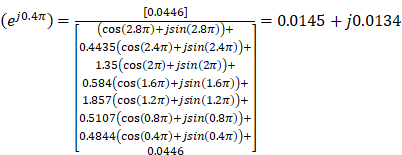
![]()
![]()
The filter Selectivity of lowpass Chebyshev I filter is obtained using equation (35)
![]()
The region of convergence ![]() of Chebyshev I lowpass filter can be obtained using
equation (24)
of Chebyshev I lowpass filter can be obtained using
equation (24)
![]()
The difference equation was obtained as:
![]()
3. RESULTS AND DISCUSSION
3.1. RESULTS
By means of Bilinear transformation techniques, the
designed Butterworth filter and Chebyshev-I digital IIR filter where the
passband gain ![]() between
between ![]() and
and ![]() ,
and stopband gain
,
and stopband gain ![]() has attenuation of
has attenuation of ![]() and sampling period
and sampling period ![]() .
The filter selectivity
.
The filter selectivity ![]() of the lowpass filter: Butterworth and
Chebyshev I were found to be
of the lowpass filter: Butterworth and
Chebyshev I were found to be ![]() and
and ![]() respectively. Also, the cutoff frequency
respectively. Also, the cutoff frequency ![]() of both the filters was computed to be
of both the filters was computed to be ![]() .
The simulation results were depicted below:
.
The simulation results were depicted below:
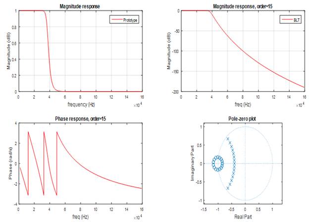
Figure 2
|
Figure 2 Frequency Response (Magnitude and Phase) and Zero-pole plot of Butterworth Lowpass Filter |
Figure 3
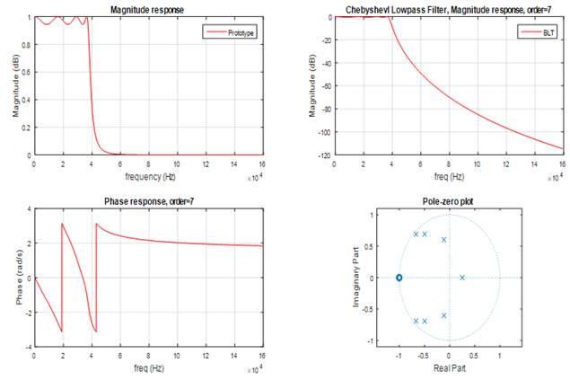
|
Figure 3 Frequency Response (Magnitude and Phase) and Zero-pole plot of Chebyshev I Lowpass Filter |
Figure 4
|
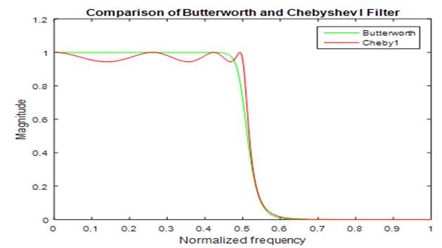
Figure 4 Comparison of Transition band of Butterworth and Chebyshev I Filter with Filter order of N=15 and N=7 respectively in absolute magnitude scale |
Figure 5
|
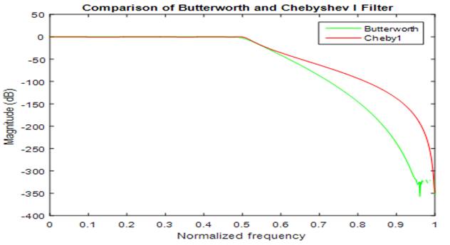
Figure 5 Comparison of Transition band of Butterworth and Chebyshev I Filter with Filter order of N=15 and N=7 respectively in dB scale |
4. DISCUSSION
Using the given specifications, the filters designed were stable as proved by the pole-zero plots depicted in Figure 2 Figure 3 The filter order and the polynomial terms of the transfer function of Chebyshev I filter in Table 1 has lower values as compared to the Butterworth filter. The transitions proved that Chebyshev I filter has sharper roll off than the Butterworth filter as depicted in Figure 4 in terms of magnitude scale and Figure 5 in terms of decibel scale. Meanwhile the phase responses also proved that IIR digital filters has nonlinear phase.
The achieved magnitude and phase response plots with respect to frequency presented in Figure 2 and Figure 3 discloses that the designed IIR digital filters employing BLT possess flat passband for Butterworth while Chebyshev I filter possess ripple in the passband and both filters possess maximally flat stopband characteristics in which they were in correspondence with prototype analogue IIR filter as depicted in the same Figures.
The ![]() of the designed filters were at the point
of the designed filters were at the point ![]() with the same bandwidth of 7.8957E4 and d.c gain
of 1 for both filters.
with the same bandwidth of 7.8957E4 and d.c gain
of 1 for both filters.
5. CONCLUSION
The achieved results were analysed to observe the performance of the filters. The obtained lowpass IIR digital filters using BLT meet the stability gauge as all the poles lie within the unit circle. Conversely, BLT has justified the potentiality of the proposed algorithm for the design of lowpass digital IIR filter to prototype analogue filter and it has fast convergence rate in term of the number of function calculations to achieve the universal solution due to its high sampling frequency which in turn has low sampling time. The efficiency of MATLAB has also been justified for depicting prototype analogue filter. The comparative analysis Table 1 shows that the Chebyshev I is better choice to reduce implementation cost. It also proved that the attenuation of the digital filter in the passband is not zero while the attenuation of the digital filter in the stopband have infinite value.
CONFLICT OF INTERESTS
None.
ACKNOWLEDGMENTS
None.
REFERENCES
Abu-hudrouss, A. (2009). Analogue Filter, Butterworth Filter. Springer 2009. © Ammar Abu-hudurouss-Islamic University, Gaza.
Aggarwal, A. Rawat, T. K. Kumar, M. & Upadhyay, D. K. (2015). Optimal design of FIR high pass filter based on L1 error approximation using real coded genetic algorithm. Engineering Sci. And Tech., 18(4), 594-602. https://doi.org/10.1016/j.jestch.2015.04.004
Aremu, O. A. Iyiade, O. J. & Ajadi, D. A. (2013). Design and Construction of Low- and High-Pass Active Filters Using Butterworth and Chebychev Techniques. 14(1), 139-149.
Balami, I. T. Muhammad, A. & Ahmed, M. (2020). Identification Of 2nd Order Digital IIR Filter From 4th Order Classical Type Using Bacterial Foraging Algorithm (BFA). 7(8), 12586-12591.
Islam, M. A. & Aktar, T. (2019). Analysis of Performance Constraints of the Infinite Impulse Response (IIR) Filter with Various Filter Algorithms and Design a Low Pass IIR filter with Desired Specifications, International Journal ofAdvanced Research in Computer Engineering & Technology (IJARCET) 8(6), 2278-1323.
Jamal, R. Cerna, M. & Hanks, J. (1996). Instruments Designing Filters Using the Digital Filter Design Toolkit. December, 1-6.
Kou, S. M. Lee B. H. & Tian W. (2006). Real-Time Digital Signal Processing: Implementation and Applications, A John-Wiley & Sons, Ltd. 2nd edition.
Kou, S. M. & Lee, B. H. (2001). Real-Time Digital Signal Processing: Implementations, Applications and Experiments with the TMS32055X, John-Wiley & Sons, Ltd.
Madisetti, E. V. K., & Williams, D. B. (1999). Digital Filtering.
Mitra, S. K. (2001). Digital Signal Processing: A Computer-based Approach. McGraw-Hill, 2nd edition.
Mitra, S.K. (2001). Digital Signal Processing - A Computer-Based Approach. McGraw-Hill, 2nd edition.
Natarajan, S. (2017). Comparison and Implementation of Different Types of IIR Filters for Speech Signal Analysis. 6(2), 550-555.
Patanavijit, V. (2020). Computer Modelling and Simulation of Bilinear Transformation on the Digital InfiniteImpulse Response Butterworth Filter. 1473-8031. https://doi.org/10.5013/IJSSST.a.20.01.14
Proakis, J. G and Monalakis D.G (2002). Digital Signal Processing Principles, Algorithms and Applications,3rd Edition, Prentice- Hall, 2002.
Prêle, D. Electronic, A. Master, S. & Electronic, A. (2021). Advanced Electronic Systems To cite this version : HAL Id.
Ramesh, K. Nirmalkumar, A. Gurusamy, G. (2009). Design of Digital IIR Filters with the Advantages of Model Order Reduction Technique. International Journal of Electronic Engineering Research 1(2), 89-100.
Saini, M. S. & Kaur, K. (2015). Design of IIR Filter Using Chebyshev. 4(6), 2703-2709.
Scarpa, G. (2013). Design of IIR filters. ENS.
Shenoi, B. A. (2006). Introduction to Digital Signal Processing and Filter Design. Published by John Wiley & Sons, Inc.
Verma, A. (2013). Algorithm for Design of Digital Notch Filter Using Simulation. 2(8), 40-43. https://doi.org/10.14569/IJARAI.2013.020807
 This work is licensed under a: Creative Commons Attribution 4.0 International License
© Granthaalayah 2014-2022. All Rights Reserved.