EFFECTIVENESS of ABRASIVE FLOW MACHINING on ADDITIVELY MANUFACTURED PARTS with VARYING CROSS-SECTION GEOMETRIES
Mehmet Ali Akeloglu 1![]()
![]() ,
Omer Eyercioglu 1
,
Omer Eyercioglu 1![]()
![]()
1 Department
of Mechanical Engineering, Gaziantep University, Gaziantep, Turkey
|
|
|
ABSTRACT |
|
|
Additive
manufacturing has become an important production method nowadays and thanks
to the developments in this field, it makes it possible to manufacture
complex parts with new practical properties. Although additive manufacturing
methods make it possible to produce parts with complex geometries, parts
produced with additive manufacturing usually have surfaces with a high degree
of roughness. Because of the negative effects on the part's fatigue life and
stress concentration caused by this rough surface, it limits its usage in
industrial applications. To enhance their surface quality, these parts
require post-processing. However, this post-processing enhancement cannot be
performed with conventional methods due to the complex geometry of the parts
produced with additive manufacturing methods. That is why, the abrasive flow
machining (AFM) process which, is an option with better results in the
surface finishing of AM parts, is used to improve the surface
characteristics. On the other hand, in the abrasive flow machining (AFM)
process, the effectiveness of material removal tends to decrease in corner
regions, particularly when the flow channel geometry involves sharp-edged
profiles such as square or hexagonal shapes. In the study, Poly Lactic Acid
(PLA) parts produced with Fused Deposition Modeling (FDM) technique in
square, hexagonal and cylindrical sections created in the same volume were
produced and subjected to AFM process and surface improvements on the corners
and edges were observed. This study aims to demonstrate, through both
analytical and experimental approaches, that the efficiency of the AFM
process is reduced at the corners of such geometries while overall surface
quality is improved. Furthermore, solution-oriented recommendations are
proposed based on the analytical evaluations to enhance process performance
in these critical regions. |
|||
|
Received 07 August 2025 Accepted 12 September 2025 Published 04 November 2025 Corresponding Author Mehmet
Ali Akeloglu, makeloglu@gantep.edu.tr DOI 10.29121/granthaalayah.v13.i10.2025.6423 Funding: This research
received no specific grant from any funding agency in the public, commercial,
or not-for-profit sectors. Copyright: © 2025 The
Author(s). This work is licensed under a Creative Commons
Attribution 4.0 International License. With the
license CC-BY, authors retain the copyright, allowing anyone to download,
reuse, re-print, modify, distribute, and/or copy their contribution. The work
must be properly attributed to its author.
|
|||
|
Keywords: Additive Manufacturing (AM), Fused
Deposition Modelling (FDM), Surface Roughness, Abrasive Flow Machining (AFM) |
|||
1. INTRODUCTION
Additive Manufacturing (AM) has become one of the most significant innovations in modern production, enabling the fabrication of parts directly from digital models through a layer-by-layer material deposition process. Unlike conventional machining or forming techniques, AM offers exceptional design flexibility, minimal material waste, and the ability to produce lightweight and geometrically complex components. These advantages have led to its increasing use in sectors such as aerospace, automotive, and biomedical engineering, where weight reduction and design optimization are critical Ngo et al. (2018), Gibson et al. (2021). Additive manufacturing technologies are generally categorized into several types, including Selective Laser Melting (SLM), Electron Beam Melting (EBM), Binder Jetting (BJ), Stereolithography (SLA), and Fused Deposition Modeling (FDM), each with distinct advantages depending on the application area Ngo et al. (2018).
Among these technologies, Fused Deposition Modeling (FDM) has gained particular attention because of its simplicity, low cost, and ability to process a wide range of thermoplastic materials. In this method, a polymer filament such as polylactic acid (PLA), acrylonitrile butadiene styrene (ABS), or polyethylene terephthalate glycol (PETG) is heated above its glass transition temperature and extruded through a nozzle to form the part layer by layer. The process provides high design flexibility and cost efficiency, making it ideal for prototyping and functional plastic components. However, the final surface quality is strongly influenced by parameters such as layer height, nozzle temperature, printing speed, and infill density, which determine how well the layers adhere and how smooth the surface appears Chacón et al. (2017). Even small variations in these parameters can cause noticeable differences in both surface appearance and mechanical performance.
Despite its practical advantages, FDM is still limited by poor surface finish compared with conventional manufacturing techniques. Because of its layer-by-layer deposition, inclined or curved surfaces exhibit the “stair-stepping effect,” producing visible ridges that increase roughness. Other factors such as filament swelling, nozzle vibration, or uneven cooling also contribute to surface waviness, voids, and dimensional inaccuracies Boschetto and Bottini (2014). These irregularities not only affect the visual quality of printed parts but also reduce their functional performance by introducing stress concentration zones, leading to decreased fatigue strength and wear resistance Gao et al. (2015). Furthermore, incomplete fusion between deposited filaments can cause micro-voids and porosity, resulting in inconsistent surface characteristics. Therefore, understanding and minimizing these surface irregularities is critical to improving the overall quality and reliability of FDM-produced components.
Although additive manufacturing has made it possible to create complex geometries with remarkable accuracy, the as-built surfaces of these parts rarely meet the quality standards required for industrial use. The printing process often leaves behind layer marks, unmelted particles, and irregular edges, which not only affect the appearance but can also lead to mechanical weaknesses such as stress concentration or premature failure. For this reason, post-processing has become an essential stage in the production chain, ensuring that additively manufactured components achieve the desired mechanical and surface performance before being placed into service Jamil et al. (2021).
Traditional finishing methods such as turning, grinding, and polishing are effective for external surfaces that are easy to reach, but they struggle when it comes to intricate internal geometries—such as curved channels, small cavities, or lattice structures. Many AM parts, especially those designed for lightweight or fluidic applications, contain such features that are nearly impossible to refine uniformly with conventional tools Parthasarathy et al. (2011). As a result, research has increasingly shifted toward non-traditional finishing processes capable of providing uniform surface improvement even in hard-to-access areas.
Among these advanced methods, Abrasive Flow Machining (AFM) has gained particular importance because of its ability to polish complex surfaces with consistent results. In AFM, a semi-solid abrasive medium is forced to flow through or around a component under controlled pressure. The mixture of viscoelastic polymer and abrasive particles acts like a flexible tool that can conform to the shape of the passage or surface being treated. As the medium moves across the material, the abrasive particles gently remove microscopic peaks, reducing surface roughness without damaging the underlying geometry. Unlike rigid tools, the abrasive flow can reach internal channels, fillets, and corners that are otherwise inaccessible, making the technique especially suitable for components with intricate geometries produced by additive manufacturing Kumbhar and Mulay (2018).
The efficiency of AFM depends on several factors, including the viscosity of the medium, type and size of abrasive particles, extrusion pressure, and flow rate. These parameters determine the rate of material removal, the level of polishing achieved, and the overall consistency of the process. Studies have shown that AFM can reduce surface roughness (Ra) by up to 80–90% on additively manufactured parts when optimized correctly, significantly improving fatigue life and corrosion resistance Ukar et al. (2013). However, it is also observed that the removal rate tends to decrease in sharp-cornered or narrow sections, where the flow velocity and abrasive concentration are not evenly distributed. Understanding and compensating for this behavior is critical for achieving uniform finishing quality in components with varying cross-sectional geometries.
For these reasons, AFM has emerged as one of the most promising post-processing methods for additively manufactured components. It offers a non-destructive and repeatable way to improve both internal and external surface finishes, bridging the gap between AM’s design flexibility and the precision required in real-world engineering applications. The process continues to evolve, with current research focusing on optimizing media rheology, developing hybrid AFM systems, and integrating computational models to better predict flow patterns in complex geometries Krolczyk et al. (2022).
In additive manufacturing, even after successful printing and preliminary surface finishing, achieving a uniform and defect-free surface across complex geometries remains challenging. The performance of any post-processing method depends not only on the process parameters but also on how the material interacts with the applied forces and flow conditions. In the case of abrasive flow machining, this interaction takes place at a microscopic level, where the abrasive-laden medium slides and deforms over the surface under pressure. Instead of cutting or grinding, material removal occurs through the combined effect of micro-shearing, plastic deformation, and slight abrasion. The abrasive particles embedded in the polymeric medium act like flexible cutting edges that repeatedly impact the surface peaks, smoothing them out over time while largely preserving the original form of the part Rhoades (1991), Jain and Adsul (2000).
The balance between media viscosity, extrusion pressure, and abrasive concentration determines how effectively the process performs. When these factors are optimized, the medium flows steadily through the component’s internal passages, producing a consistent polishing action. However, when the flow path includes abrupt transitions or sharp corners, the behavior of the medium changes noticeably. Flow velocity tends to decrease near the corner regions, reducing shear stress and the number of active abrasive contacts with the surface Sharma and Jain (2012). As a result, these areas exhibit lower finishing efficiency and retain higher surface roughness compared to flat or gently curved regions.
This study focuses precisely on that phenomenon. By examining parts with square, hexagonal, and circular cross-sections, it aims to understand how geometric complexity influences the local performance of the AFM process. Both analytical and experimental approaches are used to evaluate the distribution of flow pressure and surface improvement across these varying profiles. The findings are expected to clarify why AFM loses efficiency in sharp-edged geometries and to guide potential process modifications for achieving more uniform surface finishing in additively manufactured components.
2. MATERIALS AND METHODS
In this study, polylactic acid (PLA) filament with a diameter of 1.75 mm was used as the base material for producing test specimens through the Fused Deposition Modeling (FDM) technique. The samples were printed under controlled process parameters to ensure dimensional accuracy and consistent surface quality. PLA was selected due to its ease of printing, stable mechanical behavior, and widespread use in additive manufacturing research. All geometries—square, hexagonal, and circular—were produced with identical volumes to maintain comparable flow conditions during the subsequent abrasive flow machining process.
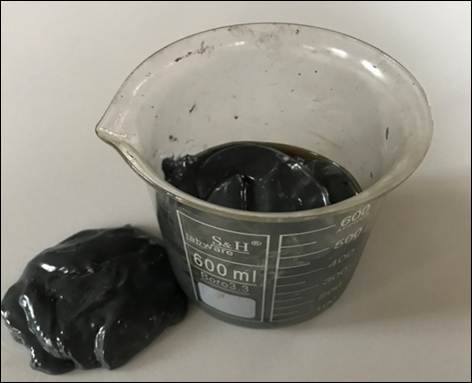
For the abrasive medium used in AFM, silicon carbide (SiC) powder with an average particle size of 240 mesh was chosen as the abrasive phase because of its high hardness and stability during repeated flow cycles. The abrasive particles were mixed with a viscoelastic polymer carrier and hydraulic oil to form a paste-like, semi-solid medium with sufficient viscosity to transmit pressure uniformly through the specimen channels. The mixture was prepared carefully to achieve a homogeneous distribution of SiC particles within the polymer base, ensuring consistent material removal throughout the process. The final appearance and texture of the prepared AFM media are illustrated in Figure 1.
Figure 1
|
Figure 1 Prepared AFM Media |
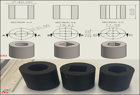
Following the preparation of the abrasive medium, three different internal geometries such as; Circular, Square, and Hexagonal, were modeled to examine how cross-sectional shape influences abrasive flow behavior and surface finishing efficiency during the AFM process. Each geometry was carefully designed to have an identical internal cross-sectional area of approximately 346.5 mm² and an internal volume of 17.325 cm³, ensuring that the flow rate, pressure distribution, and overall media volume remained comparable among the specimens. The circular channels provided a smooth and continuous path for the abrasive medium, while the square and hexagonal designs contained sharp corner regions that could potentially disturb the flow uniformity and reduce the effective contact between abrasive particles and the surface. These corners were of particular interest, as they tend to experience localized reductions in shear stress and abrasive impact density.
All three geometries were produced using the same Fused Deposition Modeling (FDM) parameters to maintain dimensional consistency and comparable internal surface quality before processing. The printed samples exhibited clearly defined inner profiles, allowing the subsequent AFM experiments to reveal how the presence of sharp corners in square and hexagonal sections affects the overall polishing uniformity and material removal performance. Part designs and produced specimens can be seen in Figure 2
Figure 2
|
Figure 2 (a). FDM Part Design. (b). Produced Specimens |
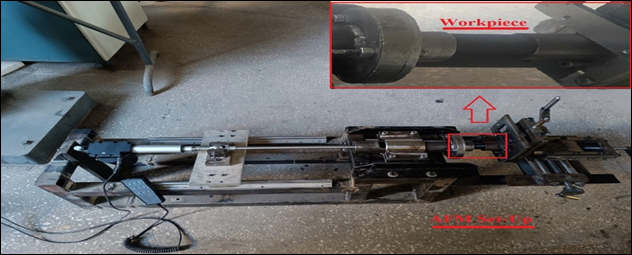
AFM set-up, which works with a horizontal one-way hydraulic piston driven with 24V DC motor with 6kN push load capacity, has been arranged for experimental work, can be seen on Figure 3 Also, experimental parameters of AFM set-up is given in Table 1
Figure 3
|
Figure 3 Experimental AFM Set-Up |
Table 1
|
Table 1 Experimental Parameters of AFM Set-Up |
|
|
Experimental Parameters |
|
|
Number of Passes |
1,5,10,20. |
|
Abrasive Type |
SiC. |
|
Abrasive Mesh Size |
240 |
|
Abrasive Concentration |
%60 wt. |
|
Plunger Pressure |
200 bar. |
Finally, the abrasive flow process was first modeled using the ANSYS Fluent software to simulate Computational Fluid Dynamics (CFD)-based AFM flow behavior and to establish a corresponding material removal model. The flow characteristics and removal patterns were analyzed to better understand the interaction between the abrasive medium and the internal surfaces of the specimens. Following the simulation phase, the AFM experiments were conducted using the designed test setup, and the experimental results were subsequently compared with the CFD analysis outcomes to assess the accuracy and reliability of the developed model.
3. RESULTS AND DISCUSSIONS
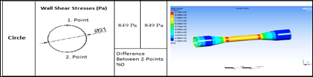
Initially, to preview the study’s results, the abrasive media flow was modeled in ANSYS Fluent software, and CFD (Computational Fluid Dynamics) analyses were performed. In these simulations, the abrasive medium was defined as a semi-non-newtonian fluid, and its rheological behavior was modeled based on experimentally obtained viscosity measurements to accurately represent its flow characteristics under pressure. The main parameter examined in the CFD analyses was the wall shear stress, which has the greatest influence on the material removal mechanism. Measurements were taken at various points along the corners and edges of the internal geometries to evaluate the effect of flow variation in these regions. The CFD results are presented in Figure 4.
Figure 4
|
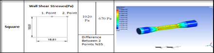
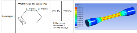
Figure 4 (a). Circular Cross-Section CFD Results. (b). Squared Cross-Section CFD Results. (c). Hexagonal Cross-Section CFD Results |
Evaluating results, Figure 4, for the circular channel, the wall shear stress values were found to be 849 Pa at both the first and second measurement points, resulting in a 0% difference between the two. This indicates that the abrasive flow was uniformly distributed along the inner surface, showing a stable and symmetrical velocity profile. The absence of sharp edges allowed the medium to maintain a consistent shear force across the circular section, leading to homogeneous material removal and an even surface finish. In the square channel, Figure 4, the wall shear stress measured 1020 Pa at the first point and 670 Pa at the second point, yielding a 35% difference between the two regions. This considerable variation suggests that the flow velocity decreased significantly near the corner areas, where the abrasive medium likely experienced stagnation zones. Consequently, the material removal efficiency in these regions would be lower, indicating that the AFM process becomes less effective near sharp edges or corners. For the hexagonal channel, Figure 4, the wall shear stress values were 990 Pa and 730 Pa, corresponding to a 26.3% difference between the two points. Although the variation is less than that of the square geometry, it still demonstrates an uneven distribution of shear stress. The multiple corners in the hexagonal shape caused partial flow deceleration, leading to less contact between the abrasive particles and the wall surface in these areas.
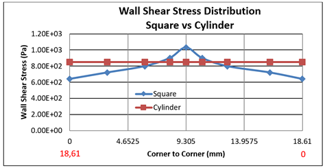
Also, the distribution of wall shear stresses was created using data along the edge between two corners, and the differences in distribution between the square section vs circular and the hexagonal section vs circular are shown in Figure 5 and Figure 6 respectively.
Figure 5
|
Figure 5 Wall Shear Stress Distribution Square vs Cylinder |
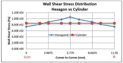
Figure 6
|
Figure 6 Wall Shear Stress Distribution Hexagon vs Cylinder |
When Figure 5 and Figure 6 are examined, The wall shear stress distributions clearly demonstrate the influence of cross-sectional geometry on the abrasive flow behavior during the AFM process. In the cylindrical channel, the flow remained stable along the entire surface, with almost no variation in wall shear stress. This indicates a uniform velocity profile and consistent abrasive-medium contact, resulting in homogeneous material removal throughout the channel.
In contrast, both the square and hexagonal geometries exhibited noticeable variations in wall shear stress between the middle regions and the corners. In the square channel, the difference between the central and corner zones was approximately 35%, while in the hexagonal geometry, it was about 26%. These fluctuations suggest that the flow accelerates near the midsection but slows down in the corner areas, where stagnation zones tend to form. As a result, the abrasive particles interact less effectively with the surface in those regions, reducing the local finishing performance.
Overall, the CFD results clearly demonstrate that the geometric complexity of internal channels has a direct influence on both the flow behavior and the polishing performance of the AFM process. Circular geometries promote a stable and uniform abrasive flow, resulting in a balanced shear stress distribution and consistent surface finishing. Similar observations were reported by Peng et al. (2023), who used CFD modeling to analyze AFM performance inside additively manufactured channels and found that curved passages promoted smoother media motion and uniform shear distribution compared to polygonal shapes. In contrast, the sharp corners present in square and hexagonal sections disrupt the flow continuity, leading to uneven shear stress and reduced finishing efficiency, particularly near the corner regions where stagnation zones tend to form. Kim et al. (2022), also observed that flow separation and deceleration occur in the corner zones of non-circular geometries, significantly lowering local polishing intensity and increasing surface roughness variation. Furthermore, Dong et al. (2021), and Uhlmann and Doits (2020), emphasized that the local viscoelastic behavior of the abrasive media directly affects the pressure–shear coupling in such regions, reinforcing the idea that media dynamics and geometry jointly determine the final surface uniformity. These findings collectively highlight that the shape of internal channels plays a critical role in determining the overall efficiency and uniformity of the AFM process for additively manufactured components.
The experimental findings obtained in this study are consistent with the trends identified through the CFD analyses and the related literature. The AFM tests conducted on additively manufactured specimens confirmed that surface improvement was highly dependent on the internal geometry of the channels. Circular samples exhibited smoother and more uniform surfaces after processing, while the square and hexagonal specimens retained relatively rougher regions near their corner zones. These experimental observations align well with the numerical predictions reported by Peng et al. (2023), and Kim et al. (2022), supporting the idea that flow stagnation and shear stress reduction in angular areas limit the material removal efficiency of the AFM process. Consequently, both the computational and experimental results emphasize that the optimization of channel geometry and media flow characteristics is essential for achieving uniform surface finishing in complex additively manufactured components.
In the experimental procedure, the Abrasive Flow Machining (AFM) process was performed for a total of 20 cycles to investigate the progressive improvement in surface characteristics. Each cycle was defined as one complete forward and reverse pass of the abrasive medium through the specimen, during which the sample was inverted between passes to ensure that both ends of the internal channel were exposed to the same flow conditions.
This alternating setup allowed uniform abrasive interaction and minimized directional bias in material removal. Surface roughness measurements were carried out using a Mitutoyo Surftest SJ-400 device after 1, 5, 10, and 20 cycles to assess the effect of cycle number on the overall surface finish. These measurements enabled the evaluation of the gradual reduction in surface roughness and the progressive enhancement observed particularly along the edge and corner regions of the test geometries.
Table 2 presents the variation of average surface roughness (Ra) with respect to the number of AFM cycles, illustrating how the overall surface texture progressively improves through repeated processing. Similarly, Table 3 lists the corresponding ten-point height (Rz) values, providing additional insight into the reduction of peak-to-valley differences across the processed surfaces.
Table 2
|
Table 2 Experimental Parameters of AFM Set-Up |
|||||
|
Form/ #AFM Cycle |
Cylinder-Ra(μm) |
Square Edge-Ra(μm) |
Square Corner-Ra(μm) |
Hexagon Edge-Ra(μm) |
Hexagon Corner-Ra(μm) |
|
0 |
9,97 |
10,11 |
11,14 |
10,55 |
11,23 |
|
1 |
8,38 |
8,85 |
9,62 |
8,74 |
9,35 |
|
5 |
6,85 |
7,24 |
7,61 |
7,1 |
7,71 |
|
10 |
4,47 |
4,86 |
5,45 |
4,65 |
5,36 |
|
20 |
1,07 |
1,24 |
2,11 |
0,98 |
1,86 |
Table 3
|
Table 3 Experimental Parameters of AFM Set-Up |
|||||
|
Form/ #AFM Cycle |
Cylinder-Rz(μm) |
Square Edge-Rz(μm) |
Square Corner-Rz(μm) |
Hexagon Edge-Rz(μm) |
Hexagon Corner-Rz(μm) |
|
0 |
46,7 |
48,6 |
54,7 |
50,8 |
51,1 |
|
1 |
42,1 |
41,8 |
45,5 |
42,8 |
44,6 |
|
5 |
29,6 |
31,4 |
33,2 |
30,4 |
32,7 |
|
10 |
20,4 |
21,2 |
24,6 |
20,2 |
23,6 |
|
20 |
4,2 |
4,5 |
6,7 |
4,3 |
5,8 |
When Table 2 and Table 3 are examined together, a clear and steady improvement in surface finish can be seen as the number of AFM cycles increases. Both the average surface roughness (Ra) and the ten-point height (Rz) values gradually decreased with each cycle, showing how repeated exposure to the abrasive medium leads to progressive smoothing of the surfaces.
After 20 cycles, the average roughness (Ra) was reduced by ≈90% for the cylindrical samples, ≈88% at the square edges, ≈81% at the square corners, ≈91% at the hexagonal edges, and ≈83% at the hexagonal corners. The Rz values followed the same pattern, with reductions of about ≈91%, ≈91%, ≈88%, ≈92%, and ≈89%, respectively. These improvements indicate that surfaces with smoother and more continuous flow paths such as cylindrical and edge regions benefited the most from uniform abrasive action during the AFM process.
In contrast, the corners of the square and hexagonal geometries showed slightly lower improvement rates, being up to 10% less effective than the edge and cylindrical regions. This reduced efficiency can be attributed to localized flow stagnation and weaker shear stresses predicted by the CFD analysis, which limit material removal in those areas. As a result, even after all processing cycles, the sharp corner regions retained surface roughness values nearly twice as high as those of the edge and cylindrical surfaces.
Overall, the findings highlight that increasing the number of AFM cycles effectively enhances the surface finish, while the complexity of the geometry still plays an important role in determining how evenly the polishing occurs across different areas of the part.
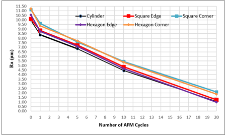
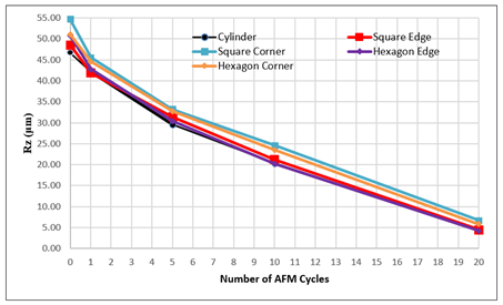
In addition, to better visualize the surface improvement trend, the variation of average surface roughness (Ra) with respect to the number of AFM cycles is illustrated in Figure 7 This graph clearly shows the progressive decrease in roughness as the number of cycles increases, highlighting the gradual smoothing effect of repeated abrasive flow. Likewise, Figure 8 presents the corresponding ten-point height (Rz) values as a function of cycle number, providing a complementary view of how the peak-to-valley surface profile becomes more uniform with continued processing.
Figure 7
|
Figure 7 Ra Values According to Number of AFM Cycles |
Figure 8
|
Figure 8 Rz Values According to Number of AFM Cycles |
The results shown in Figure 6 and Figure 7 demonstrate a clear and consistent reduction in both Ra and Rz values as the number of AFM cycles increases. This steady decline highlights the progressive smoothing effect of repeated abrasive flow on all geometries. The cylinder and edge regions show smoother and more uniform improvements, while the corner areas of the square and hexagonal samples exhibit slightly slower reductions in roughness. This behavior can be linked to the flow characteristics observed in the CFD simulations—particularly the lower shear stress and flow stagnation in sharp-cornered regions—which make the abrasive action less effective in those areas. The close relationship between the Ra and Rz trends suggests that surface peaks and valleys are reduced proportionally, indicating a balanced and stable polishing process rather than random abrasion. This uniform decline shows that the abrasive medium maintained consistent flow energy and shear distribution throughout the process, especially in circular and smooth-edged geometries where the flow remains steady. Similar behavior has been reported in previous research. Somashekhar et al. (2014), found that abrasive flow loses momentum near corners, causing lower finishing performance in complex cavities. Likewise, Rhoades (1991), observed that circular cross-sections sustain higher and more stable wall shear stress compared to polygonal ones, leading to improved surface uniformity.
Ultimately, these findings reveal a strong connection between surface roughness reduction and the material removal rate (MRR). Geometries that promote uniform flow and steady shear stress achieve higher MRR and faster surface refinement, whereas sharp corners—where the flow energy dissipates—exhibit lower MRR and reduced polishing efficiency. In summary, achieving a consistent MRR depends not only on the number of AFM cycles but also on optimizing the geometry and flow characteristics to ensure uniform material removal across the entire surface.
Figure 9
|
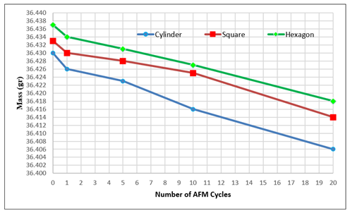
Figure 9 Mass-Based Material Removal Rate Relative to the Number of AFM Cycles |
The variation of the Material Removal Rate (MRR) over the course of the AFM process is illustrated in Figure 9, showing how the specimen mass changes with the number of processing cycles for the cylindrical, square, and hexagonal geometries. As seen in the figure, all samples experience a steady decrease in mass as the number of AFM cycles increases, confirming that continuous material removal takes place throughout the process. However, the rate of this removal is not constant—it is initially high and gradually slows down as the surfaces become smoother and more refined.
During the first few cycles, the abrasive medium removes a larger amount of material because the surface still contains sharp peaks and irregularities. These asperities offer higher resistance to the flowing medium, resulting in more intense abrasive action and higher local shear stresses. As the surface becomes progressively polished, the frictional contact between the medium and the workpiece diminishes, leading to lower removal efficiency. This shift marks the transition from an initial aggressive abrasion phase to a stabilized polishing phase.
The mass-based results show that the cylindrical specimens achieved the highest total material removal, with an average rate of about 0.0012 gr per cycle, while both the square and hexagonal specimens exhibited slightly lower rates around 0.001 gr per cycle. This difference reflects the superior flow uniformity within circular geometries, where the abrasive medium maintains steady velocity and shear stress. In contrast, the corner regions in square and hexagonal sections restrict flow movement, reducing local material removal and contributing to the slower decline in total mass.
These observations align with earlier surface roughness findings Figure 6 and Figure 7 and are consistent with the conclusions of Somashekhar et al. (2014), and Rhoades and Jain (2020), who emphasized that higher flow uniformity and shear distribution lead to better finishing and higher MRR. Likewise, Jain and Adsul (2000), reported that MRR tends to decrease exponentially with each pass as the abrasive interaction weakens, while Kumar et al. (2022) confirmed that the majority of material removal occurs during the early stages of AFM, after which only micro-polishing dominates.
Overall, the results demonstrate that AFM achieves its most effective material removal during the first few cycles, corresponding to the phase where surface peaks are rapidly eliminated. As the surface smooths and resistance decreases, the MRR stabilizes at a lower, consistent level. This pattern reveals that the geometry of the internal channel plays a critical role in defining not only surface finish quality but also the efficiency and consistency of material removal per cycle across different shapes.
4. CONCLUSIONS
Based on the overall findings, it can be concluded that the Abrasive Flow Machining (AFM) process provides a highly effective surface finishing method for additively manufactured components, achieving up to 90% improvement in surface roughness across all geometries. The CFD analyses and experimental results collectively demonstrate that smoother and more continuous geometries, such as cylindrical channels, promote stable flow distribution, resulting in uniform shear stress and higher Material Removal Rates (MRR). Conversely, geometries with sharp corners or varying internal passages exhibited a 10–15% decrease in process efficiency due to localized flow stagnation, pressure loss, and lower wall shear stresses. This reduction in flow energy directly affected material removal uniformity, leading to slightly rougher surfaces in the corner regions. Despite this limitation, the study confirmed that AFM remains a powerful and controllable method for enhancing surface quality in complex internal geometries. To further improve its performance in angular regions, flow-directing design modifications or localized pressure-enhancement approaches can be implemented to maintain higher abrasive energy and achieve consistent polishing throughout the component.
CONFLICT OF INTERESTS
None.
ACKNOWLEDGMENTS
None.
REFERENCES
Boschetto, A., & Bottini, L. (2014). Surface Improvement of Fused Deposition Modeling Parts by Barrel Finishing. Rapid Prototyping Journal, 20(1), 24-31.
Chacón, J. M., Caminero, M. A., García-Plaza, E., & Núñez, P. J. (2017). Additive Manufacturing of PLA Structures using Fused Deposition Modelling: Effect of Process Parameters on Mechanical Properties and their Optimal Selection. Materials & Design, 124, 143-157. https://doi.org/10.1016/j.matdes.2017.03.065
Dong, Z., Shen, J., & Chen, G. (2021). Study on Machining Mechanism of High-Viscoelastic Abrasive Flow Machining for Surface Finishing. Journal of Materials Processing Technology, 293, 117055.
Gao, W., Zhang, Y., Ramanujan, D., Ramani, K., Chen, Y., Williams, C. B., Wang, C. C., Shin, Y. C., Zhang, S., & Zavattieri, P. D. (2015). The Status, Challenges, and Future of Additive Manufacturing in Engineering. Computer-Aided Design, 69, 65-89. https://doi.org/10.1016/j.cad.2015.04.001
Gibson, I., Rosen, D. W., & Stucker, B. (2021). Additive Manufacturing Technologies: 3D Printing, Rapid Prototyping, and Direct Digital Manufacturing. Springer.
Jain, V. K., & Adsul, S. G. (2000). Experimental Investigations into Abrasive Flow Machining (AFM) of Complex Cavities in AISI 316 Stainless Steel Workpieces. International Journal of Machine Tools and Manufacture, 40(7), 1003-1021. https://doi.org/10.1016/S0890-6955(99)00114-5
Jamil, M., Khan, A. M., Sarfraz, S., Zhao, Z., & Ahmed, N. (2021). A Review on Post-Processing Techniques for Additive Manufactured Components. Advances in Mechanical Engineering, 13(4), 1-22.
Kim, D., Park, J., & Lee, J. (2022). Characterization of Deburring by Abrasive Flow Machining using CFD Simulation. Applied Sciences, 12(4), 2048. https://doi.org/10.3390/app12042048
Krolczyk, G. M., Królczyk, J. B., Wojciechowski,
S., Maruda, R. W., & Stachowiak,
G. W. (2022). Finishing
Techniques for Additive Manufactured Components: A Comprehensive Review. Tribology International,
168, 107446.
Kumar, R., Somashekhar, K. P., & Ramachandran, N. (2022). Influence of Process Parameters on Material Removal rate and Surface Roughness in Abrasive Flow Finishing. Materials Today: Proceedings, 62, 1482-1490.
Kumbhar, N. N., & Mulay, A. V. (2018). Post Processing Methods used to Improve Surface Finish of Products Which are Manufactured by Additive Manufacturing Technologies: A Review. Journal of the Institution of Engineers (India): Series C, 99(4), 481-487. https://doi.org/10.1007/s40032-016-0340-z
Ngo, T. D., Kashani, A., Imbalzano, G., Nguyen, K. T. Q., & Hui, D. (2018). Additive manufacturing (3D printing): A Review of Materials, Methods, Applications and Challenges. Composites Part B: Engineering, 143, 172-196. https://doi.org/10.1016/j.compositesb.2018.02.012
Parthasarathy, J., Starly, B., & Raman, S. (2011). A Design for the Additive Manufacturing Process for Customized Orthopedic Implants. Journal of Manufacturing Processes, 13(2), 160-170. https://doi.org/10.1016/j.jmapro.2011.01.004
Peng, Z., Gao, J., Li, X., & Sun, Y. (2023). Novel Insights into Abrasive Flow Machining Uniformity for Internal Channels. International Journal of Mechanical Sciences, 249, 108268.
Rhoades, L. J. (1991). Abrasive Flow Machining: A Case Study. Journal of Materials Processing Technology, 28(1-2), 107-116. https://doi.org/10.1016/0924-0136(91)90210-6
Rhoades, L. J., & Jain, V. K. (2020). Flow
Field and Surface Finishing Uniformity
Analysis in Abrasive Flow Machining.
Journal of Manufacturing Processes,
56, 1125-1136.
Sharma, V., & Jain, V. K. (2012). Analysis of Media Flow Behavior and Finishing Mechanism in Abrasive Flow Machining (AFM) Process. Wear, 274-275, 289-297.
Somashekhar, K. P., Ramachandran, N., & Kumar, M. (2014). Experimental and CFD Analysis of Abrasive Flow Machining of Complex Cavities. International Journal of Machine Tools and Manufacture, 84, 45-57. https://doi.org/10.1016/j.ijmachtools.2014.04.003
Uhlmann, E., & Doits, M. (2020). Modelling the Abrasive flow Machining
Process on Advanced Ceramic Materials. Precision Engineering, 66, 161-171.
Ukar, E., Lamikiz, A., del Val, J., & Lopez de Lacalle, L. N. (2013). Laser Polishing of Tool Steel Components Manufactured by Selective Laser Melting. Physics Procedia, 41, 875-880.
 This work is licensed under a: Creative Commons Attribution 4.0 International License
© Granthaalayah 2014-2025. All Rights Reserved.