THE EFFECT OF ARC STUD WELDING PARAMETERS ON MECHANICAL PROPERTIES OF DOCOL 1500M ADVANCED HIGH STRENGTH STEEL WELDING JOINTS
Omer Eyercioglu
1![]()
![]() ,
Tamer Ucar 2
,
Tamer Ucar 2
1 Department
of Mechanical Engineering, Gaziantep University, Gaziantep, Turkey
|
|
|
ABSTRACT |
|
|
Arc stud
welding method is a welding method that takes advantage of the arc's ability
to melt metals. Stud welding is an easy and fast welding method that is
generally applied to surfaces where threading is problematic
and welding is difficult. Docol 1500 martensite
materials are high-strength steels with high tensile strength up to 1700 MPa
and good ductility. These type of materials provide
high efficiency, especially in the automotive industry, in terms of both
vehicle lightness and advanced crash protection. In this study, the
weldability of threaded studs made of 20MnB4 grade carbon steel was
investigated using the arc stud welding process on Docol
1500M plate. The arc stud welding process was carried out using a ceramic
ferrule at different combination values with electric current values ranging
between 300A and 500A and different welding times ranging from 0.125 seconds
to 0.300 seconds, as well as variable welding parameters such as 3mm plunge
value and 5.9mm lift distance. With the experimental study, the most suitable
welding parameters were try to determined according
to the size and properties of the materials to obtain a quality welded. At
the end of welding process, the effects of arc stud welding parameters such
as welding current, welding time, plunge and lifting distance on mechanical
and microstructural properties were experimentally investigated. |
|||
|
Received 07 June
2024 Accepted 10 July 2024 Published 05 August 2024 Corresponding Author Omer Eyercioglu, eyercioglu@gantep.edu.tr
DOI 10.29121/granthaalayah.v12.i7.2024.5730 Funding: This research
received no specific grant from any funding agency in the public, commercial,
or not-for-profit sectors. Copyright: © 2024 The
Author(s). This work is licensed under a Creative Commons
Attribution 4.0 International License. With the
license CC-BY, authors retain the copyright, allowing anyone to download,
reuse, re-print, modify, distribute, and/or copy their contribution. The work
must be properly attributed to its author.
|
|||
|
Keywords: Arc Stud Welding, AHSS, Docol 1500M, 20MnB4, Joint Strength, Tensile Strength,
FEA |
|||
1. INTRODUCTION
There are various processes for joining studs to plates or structurally dissimilar materials in welding applications such as resistance welding, friction welding, and stud arc welding are the most frequently used applications. Stud arc welding is generally the fastest method and is particularly advantageous in production efficiency and threaded s in multiple weld fabrications. The arc stud welding method was first used after World War I at the New York Naval Shipyard in the United States. It was later widely used in the construction of military aircraft carriers and the construction industry Cary (2004). Arc Stud Welding (ASW) is generally used to join threaded or threadless metal fasteners to the base metal according to their purpose and usage areas and provides optimum benefit in cases where threading is required after welding. In addition, threaded fasteners can be welded directly, and the necessary screw or bolt-nut connection assemblies can be made in a short time and with little labor. Some factors affect the quality and performance of arc stud welding, these factors are; Cleaning of the surfaces to be welded, properties of the welding machine, Welding gun and equipment to be used, current value, plunge, welding time, structural features other than the dimensional properties (diameter and thickness) of the materials to be welded, welding position, welding procedure, and environmental factors. Each of the factors has a direct impact on weld quality performance.
Yilmaz & Hamza (2014) examined the effects of welding parameters such as current, time, plunge and lift on microstructural properties using AISI 304 quality base material and the same quality stud material. As a result of experimental studies, it has been observed that as the stud diameter increases, more welding current and welding time are needed, and the current, plunge and lift height are decisive in terms of tensile strength. It was also determined that low current and time factors cause insufficient melting, and high current and time values cause the weld to burn. They concluded that current and time factors have an impact on the penetration depth. Except this, it was seen that at high currents and times, the hardness, melting and solidification values in the weld area were higher than the base metal and lower at the weld center line.
Hsu & Mumaw (2011) combined M6 studs made of mild steel on USIBOR, bare boron, HC500C, and AHSS quality materials with different thicknesses and coatings by arc welding method, observed their weldability and evaluated the results comparatively. The results of the study were interpreted separately for each different experiment. As a result of the studies, it has been determined that the AHSS welded quality and the most effective welding parameters vary depending on the steel type, thickness value, and coating. It has been observed that high and low lift values for mild steel material affect the working tolerance and quality. It has been determined that uncoated boron steel has the best welding quality, and poor welding strength is obtained as a result of increasing the lifting settings. It has been observed that Usibor steel has a weaker connection than uncoated boron steel in terms of weldability, and although the welding process is performed slowly and at low temperatures, boron steel provides a more successful connection in terms of weld strength. It was also determined that due to the relation between weld strength and melt-through hole, HC500C had the worst weldability properties.
Algodi et al. (2023) joined AISI 1106 steel stud to AISI 1045 base metal by arc stud welding method using 200A and 400A welding currents and 1-2 seconds welding times and examined the effects of these parameters on microstructure and mechanics. In terms of fracture types, it was observed that interface fracture between the stud and the base metal, pullout fracture on the base metal, and fracture from the stud shank. It was observed that the microstructure in the weld zone was primarily composed of equiaxed ferrite grains and pearlite containing a small amount of ferrite, while the fusion zone consisted of fine-grained ferrite. During application, it was recommended to use ceramic rings for nails with a diameter over 12 mm and also to use shielding gas if the weld pool is affected by the atmosphere.
Yılmaz et al. (2016) determined that welding parameters are important for a quality weld connection and should be adjusted appropriately according to the material dimensions. For this, they developed a mathematical model between appropriate source parameters and input data. They predicted the tensile strength of weld joints with the Adaptive Neural Network Based Fuzzy Inference System (ANFIS) model they developed. Using stud diameter, current, time, lift height and plunge amount as input data, they prepared test sets and performed 45 different tensile tests. They developed an (ANFIS) model using the experimental results and increased the number of trials using Trimf, Gauss and Bell function types. They used statistical data metrics such as R2, MAE and MSE to evaluate the accuracy of the models and found that the learning performance of the types of functions used was high. They determined that the best model among the models was Trimf and that the function number model was shaped as 2-2-3-2-3 and reported the statistical values of the model as R2=0,87, MAE=43,67 ve MSE=3353,66. The Gbell function model was determined to be an inappropriate function type and the R2 coefficient of determination and its value were found to be below 0.7. At the end of this study, they concluded that the models created with ANFIS can give appropriate welding parameter values according to the stud diameter to obtain a quality weld.
Eyercioglu et al. (2021) examined the temperature gradient, bending loads and spring back behavior by performing V-bending tests at different temperatures on the 2 mm thick Docol 1500 Marteniste material. As a result of the experimental study, it was concluded that increasing the local heating values reduced the punch loads, no cracks were observed after bending, and increasing the bending temperature reduced the amount of spring back.
Küçüktürk et al. (2022) have investigated the effects of heating temperature and bending angle on spring back after bending in the V-bending process of Docol 1400 steel sheets. As a result of the study, analysis showed that spring back decreased linearly in twisting operations performed under high temperatures, and that there was a decrease in the mechanical properties of the material in the heated twisting zone between room temperature and 600°C.
In this study, the weldability of threaded studs made of 20MnB4 grade carbon steel was investigated using the arc stud welding process on the Docol 1500M plate. The arc stud welding process was carried out using a ceramic ferrule at different combination values with electric current values ranging between 300A and 500A and different welding times ranging from 0.125 seconds to 0.300 seconds, as well as variable welding parameters such as 3mm plunge value and 5.9mm lift distance. With the experimental study, the most suitable welding parameters were determined according to the size and properties of the materials to obtain a quality weld. At the end of the welding process, the effects of arc stud welding parameters such as welding current, welding time, plunge, and lifting distance on mechanical and microstructural properties were experimentally investigated.
2. ARC STUD WELDING PROCESS
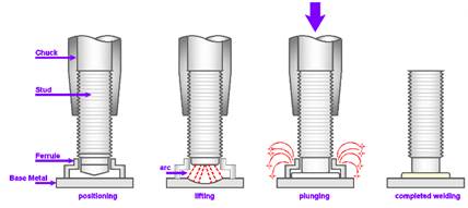
The arc stud welding method takes advantage of the arc's ability to melt metals. Stud welding is an easy and fast welding method generally applied to surfaces where threading is problematic and welding is difficult. Operation is started when a stud is connected to the welding gun and a ceramic ring is attached and positioned on the workpiece. Welding amperage and welding time are adjusted on the machine according to the stud material quality, diameter, workpiece material quality, and thickness. A mechanism at the end of the welding gun lifts the stud to adjust its plunge distance. A low-current derivative arc is ignited between the stub tip and the workpiece. As a result of the ignition of the secondary arc, the main arc is ignited between the stub tip and the workpiece. The stud and workpiece melt due to the main arc effect. At the end of the set welding time, the stud plunges into the workpiece and the molten areas combine, afterwards power supply is cut off and the weld pool congeals and cool down. The welding operation is completed and the welding gun is lifted from the stud and the ceramic ferrule is removed. The application principles of the Arc Stud Welding process can be seen in the Figure 1 Chambers (2001).
Figure 1
|
Figure 1 Illustration of All Stages of Arc Stud Welding |
It was used Docol 1500M sheet metal plate as the base material in this study. Technically Advanced High Strength Steel expresses to new technology steel that provides high strength (up to 1700 MPa) and durability without changing formability, which is very important during manufacturing processes. While AHSS provides high strength, it also helps reduce cost, which is one of the most important factors in engineering. It also improves the basic building blocks of production such as quality, efficiency, emissions, manufacturability and durability. AHSS materials provide excellent results against all these demands, thanks to their structural properties. In addition to having good ductility and strength values thanks to their multiphase microstructure, AHSS materials can both maintain their easy shaping feature and meet the expected material performance thanks to these properties.
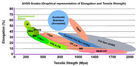
There is a special heat treatment cycle that produces a "quenching and partition" response in steel and has attracted great attention recently Baluch et al. (2014), Edmonds et al. (2006). The quenching and partition thermal transformation creates a ferritic martensitic structure rich in carbon and high in austenite. The austenite structure retained in steels as a result of this thermal transformation can be useful in various automotive applications, especially in parts that require energy management and resistance to fracture Matlock & Speer (2010). The ductility diagram of advanced high strength steels can be seen in the Figure 2 Baluch et al. (2014)
Figure 2
|
Figure 2 Steel Strength Ductility Diagram for Today’s AHSS Grades |
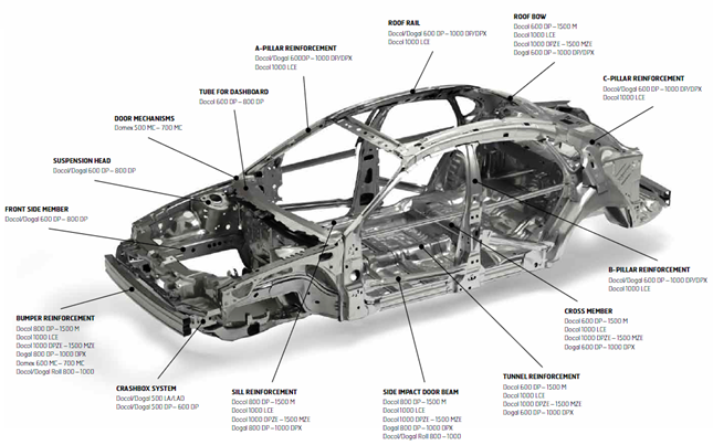
The usage areas of high-strength steels, especially used in automotive production, in vehicles are shown in Figure 3 Baluch et al. (2014)
These newer steels have increased strength and formability achieved through the development of more complex microstructures through controlled cooling processes. The first generation of these AHSS is ferrite based and these advanced types of steel are basically as follows; Dual phase (DP), Ferritic, Bainitic (FB), including stretch-flangeable (SF), Complex phase (CP), Martensitic (MS), Transformation-induced plasticity (TRIP), Hot-formed Cora & Koç (2014).
Figure 3
|
Figure 3 Typical AHSS Materials Used on Automotive |
3. EXPERIMENTAL STUDY
3.1. The Base Plate and The Stud Materials
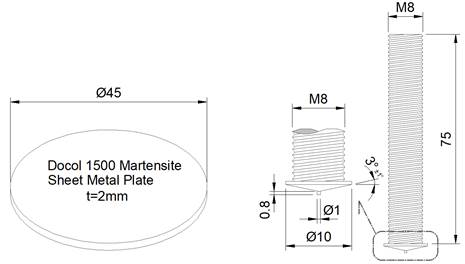
In the experiments, 2mm thickness, Ø45mm sheet metal from Docol 1500M base metal, 20MnB4 quality Ø8mm, and 75mm length fully threaded studs were welded using the arc stud welding method by EN ISO 14555 standards ISO (2005). Docol 1500M allows for increased crashworthiness, lightweight design, and cost-efficient production methods for the automotive industry, especially in side impact protection, bumper areas, and many other critical structures. Yield strength values are between 1220-1520 MPa and tensile strength values are characterized between 150-1750 MPa. The chemical composition and mechanical properties of the 20MnB4 and the Docol 1500m raw material which were used are given in Table 1 and Table 2 respectively Baluch et al. (2014), Laber & Koczurkiewicz (2015).
Table 1
|
Table 1 The Chemical Composition of Stud and Base Plate |
|||||||
|
Material |
C |
Si |
Mn |
P |
S |
Cr |
Cu |
|
20MnB4 |
0.18-0.23 |
0.30 |
0.90-1.20 |
0.025 |
0.025 |
0.30 |
0.25 |
|
Docol 1500M |
0.28 |
0.40 |
1.30 |
0.020 |
0.010 |
1.00 |
0.20 |
Table 2
|
Table 2 The Mechanical Properties of Stud and Base Plate |
|||
|
Material |
Yield
Rp0.2 MPa |
Tensile
Rm MPa |
Elongation |
|
20MnB4 |
897
(≥) |
659
(≥) |
A
(%) 31 |
|
Docol 1500M |
1220-1520 |
1500-1750 |
A80
(%) 3 |
The Ø8mm fully threaded studs used in the
experiment were made of 20Mn4 quality steel and heat treated. The quality of
the studs is 8.8 and is particularly preferred in designs where threading after
welding is difficult. With the help of threaded studs applied by the stud
welding method, it provides the advantage of easy and fast applicability and
the possibility of making bolted connections with a single welding point. Stud
welding processes in threaded studs and bolts provide great facilities in the automotive
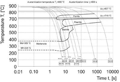
industry and shipbuilding. Figure 4 shows the CCT diagram of the standard 20MnB4
material from the literature Laber
& Koczurkiewicz (2015). According to this diagram, Ac3 = 827°C, Ac1 = 719°C. Furthermore, Ms =
385°C and Mf = 225°C. The conversion ranges of the
ferrite, perlite, and bainite phases are also indicated.
Figure 4
|
Figure 4 The CCT Diagram of 20MnB4 |
3.2. Finite Element Modelling
Finite Element Method (FEM) was utilized to simulate and analyze the joint strength of the stud weld structure. Both 2D and 3D structural analyses were carried out by using DEFORM software. The material properties and boundary conditions were defined by using the commercial finite element code and automatic mesh generated for the models. The solution algorithm of the Newton-Raphson iteration was employed.
4. METHODOLOGY AND EXPERIMENTAL PROCEDURE
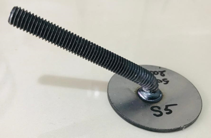
In the experiments, the best amperage, welding time, immersion amount, and lifting height were tried to determine a quality weld (in terms of joint strength). Tensile and bending tests were applied to the welded joints and the microstructure of the weld area of the best welded sample was examined. Some preliminary preparations were made to obtain the most accurate and scientific results from the studies carried out during the application of these experiments. The preparations made can be summarized as follows; material selection, supply of studs with appropriate welding dimensions, supply of the necessary mixture gas to protect the weld pool, supply of ceramic ferrules, and stud welding machine.
Figure 5
|
Figure 5 Demonstration of Stud and Base Plate Before Welding Process |
4.1. Arc Stud Welding Operations
Selecting process
parameters and levels to obtain a high-quality weld is of great importance four
different parameters have been considered during the welding process. These
parameters are amperage, welding time, plunge, and lift height. Amperage and
welding time as well as plunge distance (mP) and Lift
(Li) can be easily adjusted digitally on the machine from the handle of the
welding gun. The arc stud welding with single-use ceramic ferrules were
performed by using SOYER BMK 16i Stud welding machine and PH 3 SRM welding gun,
under different currents and welding times. During performing parameters such
as the plunge and lift height were kept constant at 3 mm and 5.9 mm,
respectively.
Figure 6
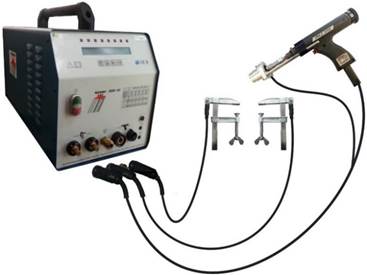
|
Figure 6 Schematic Illustration of the Experiment Set-Up |
Table 3
|
Table 3 Welding Process Parameters and Corresponding Levels |
|||||
|
Sample
No |
I
(Amp) |
tw (sec) |
mP (mm) |
Li
(mm) |
Welding
Conditions |
|
S1 |
500 |
0,220 |
3 |
5,9 |
|
|
S2 |
500 |
0,250 |
3 |
5,9 |
|
|
S3 |
350 |
0,280 |
3 |
5,9 |
|
|
S4 |
350 |
0,270 |
3 |
5,9 |
Clean
surface |
|
S5 |
500 |
0,200 |
3 |
5,9 |
|
|
S6 |
500 |
0,150 |
3 |
5,9 |
Ceramic
ferrules were used during implementation |
|
S7 |
500 |
0,175 |
3 |
5,9 |
|
|
S8 |
350 |
0,275 |
3 |
5,9 |
|
|
S9 |
500 |
0,125 |
3 |
5,9 |
|
|
S10 |
350 |
0,300 |
3 |
5,9 |
|
First, the main material was cut in circular form with a Ø45mm on the Docol 1500M laser cutting machine, the surface of the base plate was cleaned of dust, foreign substances and oils, and then meticulously cleaned and dried using ethyl alcohol. SOYER BMK 16i Stud arc stud welding machine parameter settings were made, Ø8mm fully threaded stud material and a disposable ceramic ring were placed on the PH 3 SRM welding gun. As seen in the table above, welding operations were carried out at welding parameters ranging from 350 amperes to 500 amperes and from 0.125 seconds to 0.300 seconds, and the plunge distance was kept constant at 3 mm and the lifting heights at 5.9 mm. 10 different welding parameters were used for welding processes, and excessive and inadequate welding conditions were excluded from the evaluation. As seen in the table above, welding operations were carried out at welding parameters ranging from 350 amperes to 500 amperes and from 0.125 seconds to 0.300 seconds, and the plunge distance was kept constant at 3 mm and the lifting heights at 5.9 mm.
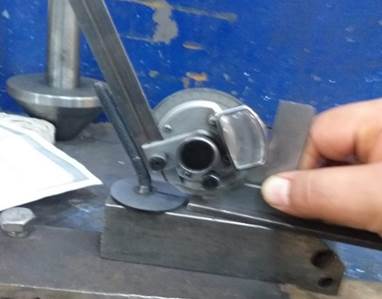
4.2. Bending Test
Bending tests were
carried out according to EN ISO 14555 standards ISO (2005). It was used a metal pipe and adjustable miter when performed the bending test, and we fasten the
sample to a vise and slowly and carefully, and then
we applied force it with a metal pipe. We continued to apply loads up to 60
degrees by controlling the bending angle from the adjustable miter. Tensile tests were applied to all samples, but only
the samples that were suitable for weld visual inspection and had high tensile
test values were subjected to bending tests.
Figure 7
|
Figure 7 Bending Application |
Figure 8
|
Figure 8 Welded Specimen After Bending |
4.3. Tensile Test
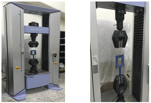
The Shimadzu brand
testing machine was used while performing tensile tests. The maximum tensile
load capacity of the machine is 600 kN, and the
uniaxial load was applied until the moment of fracture of the test pieces and
until fracture occurred in the samples with 2 mm/minute advances, and then the
strength values were recorded. Obtained strength values had been described as
joint strength because fracture mode was taken place on the base metal. Welded
specimens are not standard tensile test specimens since one side is a stud and
the other side is a plate. Therefore, a special apparatus was used to perform
the tensile test of welded samples Yilmaz & Hamza (2014).
Figure 9
|
Figure 9 Shimadzu Brand Testing Machine and Holding Apparatus |
4.4. Microstructure Evaluation and Micro-hardness Tests
Among the welded
samples, the best welded joint sample is S5. The S5 sample was cut
perpendicular to the welding direction and the sample was prepared by standard
metallographic processes such as grinding, polishing, and etching with 4% Nital
for 5-10 seconds at room temperature. After pre-examination procedures were
completed, welding zones on samples were observed closer, and the distinctions
over the welding zone were more clearly recognized. It is important to perform
microstructure analysis to improve the strength, interface and heat affected
zone properties of the weld metal. In another sense, significant changes in
microstructural properties affect the mechanical properties of the weld joint.
The change in grain size in the microstructure affects the weld joint quality MI et al. (2008). To clearly see the microstructure of the
samples, grinding and polishing processes were applied using different grit
sandpapers and silk fabric, and then etching was applied to the finished
surface of the samples. Vickers tester was used for micro-hardness measurement,
a square-based diamond pyramid, 136° face angle, 1 kg applied load, and a
loading time of 10 seconds during the test were used for testing. Vickers
hardness test was performed according to EN ISO 6507 standard ISO (2005). Nikon microscope with 500X magnification
was used to show the changes in the microstructure of weld metal, interface
zone, and HAZ Yilmaz & Hamza (2014). The distribution of hardness values and
strength values obtained are also shown in the graph.
5. RESULTS AND DISCUSSIONS
5.1. Welding Performance of the Samples
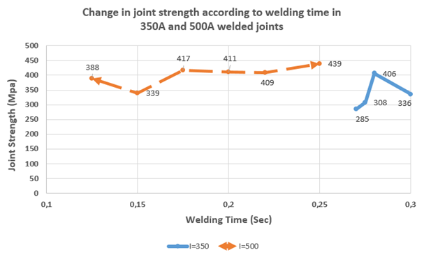
It can be seen
changing of joint strength with respect to welding time that joint the strength
values of 10 different welded samples obtained as a result of different welding
times between 0.15 seconds and 0.300 seconds for 350A and 500A welding currents
are given in the graph below;
Figure 10
|
Figure 10 Graph of arc Stud Welding Joint Strength Values of Welded Samples Applied at 350A and 500A Welding Current Values and Different Welding Times. |
5.2. Tensile Test Results
The minimum joint
strength was recorded at 0.125 and 0.150 seconds at 500A welding current is
approximately 388 MPa and 339 MPa, respectively. Low strength values are
thought to be due to insufficient melting of the base metal due to insufficient
welding time. The joint strength value increases with the increase in welding
time, accordingly, it reached 411MPa and 409Mpa values at 0.200 and 0.225
seconds of welding time, respectively. The max. joint strength value was
recorded as 439MPa at 500A and 0.250 welding time. According to these
evaluations, the tensile strength of the weld was found to be higher than the
tensile strength of the base metal and the stud metal and it was observed that the some samples have good joining performance in terms of
welding. Increasing the strength value means, in a sense, the grain size
increases with the increase in heat input. The strength values recorded at
0.270, 0.275, 0.280, and 0.300 seconds at 350A welding current are 285MPa,
308MPa, 406MPa, and 336MPa, respectively. At low current values, just like at
low welding time, the strength values are not very high due to insufficient
heat input and incomplete melting. This test are
showing us that for obtaining a good welding joining performance and a higher
tensile strength values, optimum welding parameters are important and also
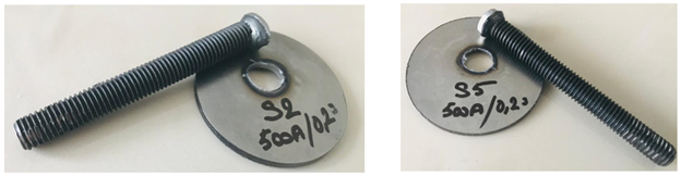
necessary. During the tensile tests performing, a pullout fracture (in the form
of a hole) was observed on the base metal. It was thought that this type of
failure was caused by the material being 2 mm thick, meaning that the base
material was quite thin in terms of thickness.
Figure 11
|
Figure 11 Fracture Mode of Samples |
5.3. Bending Test Results
On the samples
which have proper welding joining that result of optimum welding parameters and
on samples which are more weaker were performed
bending test according to EN ISO 14555 International Standart
Welding-Arc sTud
Welding of Metallic Materials. (2014).
Table 4
|
Table 4 Results of Bending Test Performed on Samples |
||||||
|
Sample |
I |
tw |
P |
L |
Location
of Fracture |
Evaluation |
|
No |
(Amp) |
(sec) |
(mm) |
(mm) |
||
|
S1 |
500 |
0,220 |
3 |
5,9 |
no
fracture |
passed |
|
S2 |
500 |
0,250 |
3 |
5,9 |
weld
zone |
failed |
|
S3 |
350 |
0,280 |
3 |
5,9 |
no
fracture |
passed |
|
S4 |
350 |
0,270 |
3 |
5,9 |
weld
zone |
failed |
|
S5 |
500 |
0,200 |
3 |
5,9 |
no
fracture |
passed |
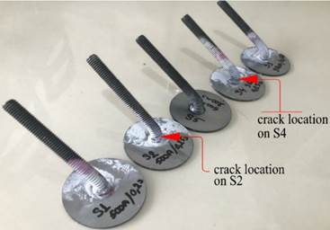
During the test,
the samples were subjected to a force appropriate to the standards, and the
bending behavior was observed. No fractures or
defects were observed in the bending tests of the samples with high tensile
strength, while slight cracks were observed in the samples with low tensile
strength. To verify the presence of cracks and defects, the samples were
subjected to liquid penetrant testing and the cracks were confirmed. These
defects may be due to the problem of centering the
stud to the base metal and the incorrect hand sensitivity of the welding
process.
Figure 12
|
Figure 12 Views of Bending |
5.4. Micro-Hardness Test Results
The micro-hardness
test has been developed for applications where the hardness of important areas
of the materials especially in welded parts and thin materials Chandler (1999). Particularly in welded joints, due to heat,
microstructural changes such as melting, cooling, and solidification of the
welded regions result in changes in the grain sizes in the structure, resulting
in different hardnesses in these affected regions. With this test, we examined
the hardness values of weld sections on our welded samples and the hardness
changes due to temperature differences in the sample. For the micro-hardness
test, the sample with the best weld quality and the highest value in terms of joint
strength was selected. The change in measured hardness values is shown in the
cross-sectional view of the welded joint below. As a result of the test that
the hardness value of the weld metal is higher than from section of HAZ and
main test materials. Furthermore, when the hardness distribution in the welded
samples is examined a soft zone was seen at the bottom
of the base material, as shown in the attached figures. For the formation of
this region, it can be said that the stud metal, which is soft during welding
is piled up into the harder base metal.
Figure 13
|
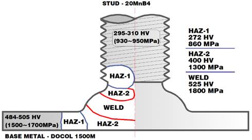
Figure 13 HAZ Regions and Distribution of Hardness and Joint Strength Values |
Hardness values on the sample were 272HV1 and 860Mpa UTS in the HAZ-1 zone, 400HV1 and 1300Mpa UTS in the HAZ-2 zone, and 525HV1 and 1800Mpa in the weld zone. The hardness of the main material Docol 1500 Martensite was measured as 484-505 HV1 and 1500-1700Mpa, while the hardness of 20MnB4 stud was measured as 295-310HV1 and 930-950Mpa UTS. The hardness of the fusion zone had been seen to be higher than the hardness of both the base material and the stud.
5.5. Finite Element Analyses Results
In addition, the
failure situation and joint strength value that caused the damage was simulated
using Deform FEM and Solid works analysis software, and the resulting failure
situation and the obtained joint strength values were verified.
Figure 14
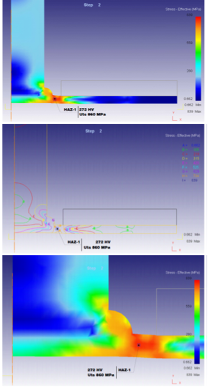
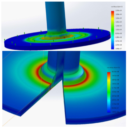
|
Figure 14 FEA Images of Loading |
5.6. Microstructure Analyses Results
It is important to
perform microstructure analysis to improve the strength, interface and heat
affected zone properties of the weld metal. In another sense, significant
changes in microstructural properties affect the mechanical properties of the
weld joint. The change in grain size in the microstructure affects the weld
joint quality MI et al. (2008).
At the bottom of Figure 15, the cross-sectional view and the selected
microstructure region of the arc stud welding connection prepared at 350 A
welding current and 0.20 s welding time are shown. Figure 15a shows
the microstructure of the left side view of the main material Docol 1500 martensite. These sections can be called parts
whose internal structure does not change during welding. This means that these
areas are not overly exposed to welding heat. Figure 15b shows
the microstructure of the upper side view of the main material Docol 1500 martensite. These regions are similar
to the microstructure on the side surface of the plate in terms of
internal structure change, except for close distances to the weld areas. Figure 15c
shows the microstructure of view of the stud material 20MnBn4. This region is
not exposed to heat. Figure 15d shows
the microstructure view of the HAZ, which is the heat-affected zone of Docol 1500M, which is the melting zone of the main
material. Generally, heat-affected zones are the most critical point of the
welded connection, fractures occur more in these regions and the
microstructures of these regions change depending on the heat input. It can be
said that the microstructure also grows and increases in grain structure. Figure 15e shows
the microstructure view of the HAZ, which is the heat-affected zone of 20MnB4,
which is the melting zone of the stud material. Figure 15f shows
the microstructure of fusion zone of the weld joint produced at 350 A current
and 0.20 second welding time.
Figure 15
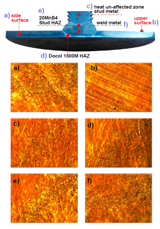
|
Figure 15 Images of the Microstructures of the Section Taken After Welding Docol 1500 Martensite Plate and 20MnB4 Quality Stud with Welding Parameters of 350 Amperes and 0.20 Seconds. (Sample No: S5) |
6. CONCLUSIONS
Among the welding
processes, arc stud welding is a successful modality in welding fully threaded
low carbon steel studs with a diameter of 8 mm and a length of 75 mm to a 45 mm
thick high-strength martensite steel plate with a thickness of 2 mm. Stud welding
application was carried out on 10 different samples and parameters between 350
amps and 500 amps welding current values and 0.125 seconds and 0.300 seconds
welding time values, and among 10 samples, 5 welded joints with the best
welding parameters were identified. Tensile tests were applied on 10 different
samples, and changing of the time with respect to joint strength was examined
on samples. Bending tests were applied on 5 different welded joints with the
best parameters, and then hardness and microstructure examination was carried
out for the welded joint which has the best parameter.
It was determined
that the most successful welding among welded connections was the one with 500A
electric current, 0.200 second welding time, 3mm plunge and 5.9mm lifting
distance. As a result of the tensile strength test, it was determined that the
rupture occurred under a maximum load of 20,695 N and the maximum joint
strength was 411MPa. The conclusions obtained as a result of the studies
conducted are as follows;
1)
In S5
welding joint which had the parameters of 500A electric current, 0.200 second
welding time, 3mm plunge, and 5.9mm lifting, a maximum 411MPa strength value
was obtained after the tensile strength test. It has been determined that the
strength value obtained here is the joint strength value instead of the
ultimate tensile strength.
2)
In
tensile test, in the S5 sample welded with 500 amperes welding current and
0.200 seconds welding time, the failure mode occurred as a
result of the load of 20695 N. The failure mode is pullout fracture,
which occurs with the formation of holes in the base material.
3)
As a
result of the bending test performed according to EN ISO 14555 standard, no
cracks or microcracks were observed either in the welding area or on the stud.
4)
Hardness
values in the sample were obtained as 272HV1 and 860Mpa UTS in the HAZ-1
region, 395HV1 and 1300Mpa UTS in the HAZ-2 region, and 525HV1 and 1800Mpa in
the welding region. The hardness of the main material Docol
1500 Martensite was measured as 484-505 HV1 and 1500-1700Mpa, while the
hardness of 20MnB4 stud was measured as 295-310HV1 and 930-950Mpa UTS. It was
observed that the hardness of the fusion zone was higher than the hardness of
both the base material and the stud.
5) When the microstructure is examined, it can be seen that the heat-affected regions have the highest temperature and the grain structure in this region increases, grows and elongates. It can be said that this microstructural change will also cause changes in the mechanical and physical properties in these regions.
CONFLICT OF INTERESTS
None.
ACKNOWLEDGMENTS
None.
REFERENCES
Algodi, S. J. M., Salman, A. A., & Al-Helli, A. H. (2023). Microstructure and Mechanical Properties of AISI 1106 /AISI 1045 Steels Drawn Arc Stud Welded Joints. Advances in Science and Technology Research Journal, 17(5). https://doi.org/10.12913/22998624/171020
Baluch, N., Udin, Z. M., & Abdullah, C. S. (2014). Advanced High Strength Steel in Auto Industry: An Overview. Engineering, Technology & Applied Science Research, 4(4), 686-689. https://doi.org/10.48084/etasr.444
Cary, H. B. (2004). Modern Welding Technology 5/e. Industrial Robot: An International Journal, 31(4), 376. https://doi.org/10.1108/ir.2004.31.4.376.3
Chandler, H. (1999). Introduction to Hardness Testing. Hardness Testing. USA: ASM International, 1-13. https://doi.org/10.31399/asm.hb.v08.a0003270
Cora, Ö. N., & Koç, M. (2014). Promises and Problems of Ultra/Advanced High Strength Steel (U/AHSS) Utilization in Automotive Industry. 7th Automotive Technologies Congress (OTEKON 2014), November, 1-8. http://dx.doi.org/10.13140/2.1.4725.0883
Edmonds, D. V, He, K., Rizzo, F. C., De Cooman, B. C., Matlock, D. K., & Speer, J. G. (2006). Quenching and Partitioning Martensite-A Novel Steel Heat Treatment. Materials Science and Engineering: A, 438, 25-34. https://doi.org/10.1016/j.msea.2006.02.133
Eyercioglu, O., Alacaci, S., & Aladag, M. (2021). Experimental Investigation of Springback of Locally Heated Advanced-High Strength Steels. Int. J. Res.-Granthaalayah, 9, 269-277. https://doi.org/10.29121/granthaalayah.v9.i3.2021.3811
Hsu, C., & Mumaw, J. (2011). Weldability of Advanced High-Strength Steel Drawn Arc Stud Welding. Welding Journal, 90(3).
ISO, E. N. (2005). Metallic Materials. In Vickers Hardness Test. Part 1: Test Method.
Küçüktürk, G., Tahta, M., Gürün, H., & Karaağaç, I. (2022). Evaluation of the Effects of Local Heating on Springback Behaviour for Ahss Docol 1400 Sheet Metal. Transactions of Famena, 46(3). https://doi.org/10.21278/TOF.463037821
Laber, K., & Koczurkiewicz, B. (2015). Determination of Optimum Conditions for the Process of Controlled Cooling of Rolled Products with Diameter 16.5 mm Made of 20MnB4 Steel. Proceedings of the 24th International Conference on Metallurgy and Materials-METAL, 364-370.
MI, K., ML, K., Biro, E., & Zhou, Y. (2008). Microstructure and Mechanical Properties of Resistance Spot Welded Advanced High Strength Steels. Materials Transactions, 49(7), 1629-1637. https://doi.org/10.2320/matertrans.MRA2008031
Matlock, D. K., & Speer, J. G. (2010). Processing Opportunities for New Advanced High-Strength Sheet Steels. Materials and Manufacturing Processes, 25(1-3), 7-13. https://doi.org/10.1080/10426910903158272
Welding-Arc sTud Welding of Metallic Materials. (2014).
Yilmaz, N. F., & Hamza, A. A. (2014). Effect of Process Parameters on Mechanical and Microstructural Properties of Arc Stud Welds. Materials Testing, 56(10), 806-811. https://doi.org/10.3139/120.110629
Yılmaz, N. F., Çakır, M. V., & Yılmaz, M. (2016). Saplama Kaynak Bağlantılarının Çekme Dayanımının ANFIS ile Modellenmesi. Çukurova Üniversitesi Mühendislik-Mimarlık Fakültesi Dergisi, 31(ÖS1), 79-88. https://doi.org/10.21605/cukurovaummfd.311889
 This work is licensed under a: Creative Commons Attribution 4.0 International License
© Granthaalayah 2014-2024. All Rights Reserved.