FLOATING OFFSHORE TURBINES - INSTALLATION METHODS
Alan Philip Crowle 1![]()
![]()
1 Naval Architect, Renewable Energy
Department, University of Exeter, (Penryn Campus), United Kingdom
|
|
|
ABSTRACT |
|
|
Floating offshore wind turbines are a possible source of large scale electricity. Fabrication and offshore installation design of these large floating structures is required to provide confidence to developers and insurers that they are constructed in a safe and cost effective manner. The design methods developed in this paper cover the substructure types such as Spars, semi submersibles, barges and TLPs. The engineering of mooring types includes catenary, taut and tension, plus turret mooring. This paper details the preparation of engineering requirements for installation vessels and large onshore cranes used for the shipyard construction of substructures for floating wind. Each installation phase, for a floating offshore wind turbine, raises issues regarding existing construction methods and the need to develop revised installation works. The engineering processes include mooring installation and connection. In addition consideration of load-out analysis, ocean transportation analysis including sea-fastening, intact stability and tow motion response. Installation analysis is required for lifting, up-ending, afloat construction, and cable lay methods. Floating
offshore wind turbines are offering a new approach to using marine resources
and this paper will provide information on how naval engineering can be used
to promote this development. |
|||
|
Received 13 January 2024 Accepted 14 February 2024 Published 29 February 2024 Corresponding Author Alan
Philip Crowle, ac1080@exeter.ac.uk DOI 10.29121/granthaalayah.v12.i2.2024.5459 Funding: This research
received no specific grant from any funding agency in the public, commercial,
or not-for-profit sectors. Copyright: © 2024 The
Author(s). This work is licensed under a Creative Commons
Attribution 4.0 International License. With the
license CC-BY, authors retain the copyright, allowing anyone to download,
reuse, re-print, modify, distribute, and/or copy their contribution. The work
must be properly attributed to its author.
|
|||
|
Keywords: Naval Architecture, Floating Wind,
Offshore |
|||
1. INTRODUCTION
The future
for floating wind is to turn the concepts from demonstration to fully
commercial developments. This paper therefore reviews the effort required to
reduce construction schedule and minimising capital expenditure (CAPEX) and
lifetime cost of energy (LCOE).
Minimising costs during construction and will assist in
reducing the CAPEX. Large floating
wind farms will enable shipyards to develop construction industry and project
management methods that will lead to rapid floating wind deployment.
Floating wind produce
electricity for use onshore, via export cables. Some floating wind provides
electricity to offshore oil and gas production facilities, to reduce their
carbon emissions. The largest floating wind farm at present is about 100MW.
There is a desire to now develop commercial projects that are around 300MW in size, to prove the concept of mass production. This will move floating wind into a commercial phase, which will give opportunities that helps to continue to build market confidence.
It is predicted that by 2050
floating wind farms will be larger than 1GW each. Floating
offshore wind turbines are being designed to generate electrical energy in
water depths of at least 60
metres. This is the current maximum depth for fixed-bottom
wind turbines. Maximum water depths for floating wind will be limited by the
design constraints on mooring systems and dynamic array export cables.
Floating offshore wind turbines are complex and the
options for structures are described in section 2. The requirements and
facilities for construction are in section 3.
Constructability is considered in section 4. Typical construction
techniques are shown in section 5 and are further developed in the facilities
construction facilities, section 6.
Risks and reliability need to be considered, section 7. The discussion and conclusions are in section
8.
Floating
wind turbines are not yet commercially viable as their construction costs are
greater than for fixed-bottom turbines. As locations for fixed-bottom
get used up then developers will consider going into deeper water and use
floating wind structures. Naval architecture methods for floating wind are
detailed in part in each section, Crowle
& Thies (2022).
The method
of analysis is by literature research, past construction experience of offshore
structures and analysing current methods of floating wind fabrication.
2. STRUCTURES ARE COMPLICATED
The complexity and large dimensions of floating offshore
wind turbines, make them sensitive to the weather conditions during fabrication
and offshore installation. The planning of the actual construction methods require turning the design into a real structure.
These construction activities use the overall term of
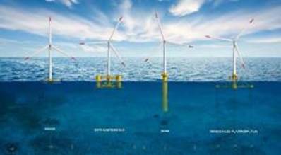
constructability. The main types of floating offshore wind turbine are can be seen in Figure 1. The
main types are the Semi-submersible, the Spar, the Barge, and the Tension Leg
Platform (TLP) substructure types. In these cases the
turbine rotates relative to the substructure, whilst the substructure does not
rotate relative to the moorings.
Figure 1
|
Figure 1 Floating Wind Types (Credit DnV) |
There are alternatives mooring arrangements under
development using a pivot buoy where the substructures rotates
on a turn table, but the turbine remains fixed relative to the substructure.
Floating offshore wind turbine (FOWT) structures are
quite expensive to fabricate and install offshore. In addition
dynamic array cables which connect the floating wind structure to the subsea
export cable require more development in order to reduce their very high
capital costs, Ramachandran et al. (2022).
Construction costs and their development schedule need more detailed
consideration. The installation is very weather dependent and so is often on
the critical path, for the renewable energy project. Good planning and good
project management in order to minimise construction
and installation time. During the design stage constructability and
installation options needs to be considered so that the FOWT is fabrication
time is minimised.
2.2. CONSTRUCTION PLANNING
Each type of floating offshore wind turbine substructures
effects the selection of construction and installation methods. In particular the substructure type results in the water
depth requirements at the load-out shipyard and at the vertical integration fit
out quay.
The overall schedule includes procurement, fitting
together of components and prefabricated items. The training of workers, the
organization and the supervision of the workers need to be developed with works
councils. Quality control, safety on site, cost estimating, work scheduling and
cost control are all part of construction engineering.
Weight control is very important for all phases of
fabrication, tow out and offshore installation of the floating wind turbines. Table 1 shows
the fabrication constraints per type are presented. Table 2 shows
the status of floating offshore wind turbines, with number deployed in
brackets.
Construction planning considers heavy lift cranes, yard
labour, high level access and transport of materials, Shu (2022). In addition the fit out of electrical, piping and mechanical
items within the structure needs to be scheduled.
Constructability uses standard methods in
order to overcome the difficulties in complicated construction. Its
scope includes ocean transport of components, fabrication, tow-out and
installation. Towing ashore for maintenance, possible relocation to another
site, or extreme event of salvage are also part of the constructability.
Eventual decommissioning of all the offshore components is also to be
considered in the design constructability meetings.
Table 3
compares fabrication and offshore installation of floating offshore wind
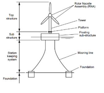
turbines (FOWT). The main components of a floating offshore wind turbine are
given in Figure 2.
Table 1
|
Table 1 Construction Restraints for FOWT |
|
|
Construction/installation
constraint |
|
|
TLP |
Low intact stability during tow |
|
Spar |
Deep draft |
|
Barge |
Motions during tow |
|
Semi-submersible |
Heavy substructure |
Figure 2
|
Figure 2 Floating Wind Turbine (Credit DnV) |
Table 2
|
Table 2 Status of Deployed Floating Wind |
|
|
Type
Country (no off) |
Material |
|
Semi-submersible,
Portugal (3) |
Steel |
|
Semi-submersible,
Scotland (5) |
Steel |
|
Spar,
Scotland (5) |
Steel |
|
Spar,
Norway (11) |
Concrete |
|
Pivot
Buoy, Portugal (1) |
Steel |
|
Pivot
Buoy, Concrete (1) |
Spain |
|
Suspended
ballast, Norway (1) |
Steel |
Table 3
|
Table 3 Comparison of Installation Ease |
|
|
Type |
Comment |
|
TLP |
Complicated
installation |
|
Spar |
Requires
solid ballast |
|
Barge |
Low
freeboard |
|
Semi-Submersible |
Installation
method well known |
3. FLOATING WIND CONSTRUCTION
The distinct stages that a floating offshore wind
structure goes through are:
·
Fabrication
·
Load-out (or float-out)
·
Vertical integration of topsides
·
Commissioning and completion afloat,
·
Ocean tow transport
·
Mooring connection
·
Subsea cable hook-up.
In constructability planning, it is essential to develop
detailed schematic drawings of each stage. Further subdivision is required of
each stage to develop small work packages that can be carried out by a small
group of workers. Structural design reports on the structural capacity under
differential loads need to be calculated. Where the substructure is afloat then
intact stability calculations are required for each stage.
Items to be considered in the planning include:
·
Substructure draft, trim and heel
·
Available water depth
·
Solid ballast requirements
·
Water ballast requirements
·
Intact stability
·
Tie-down sea-fastenings on HTV
·
Hydrodynamic response during tow,
·
Transport fatigue
·
Effect of temperature on valves
·
Wind loads at all stages
·
Wave and current forces during tow
·
Snap loads of mooring lines
·
Clearance under the keel
·
Damage cases
·
Poor ballast control
·
Vortex shedding
·
Welding temporary attachments
An overall check needs to be made of the whole
construction sequence to ensure integration. The coordination of all steps and
stages are required during subassembly, construction, offshore installation and commissioning.
In floating offshore wind turbine construction, there is
a need for development of lifting equipment and any special instrumentation.
New temporary steel structures and rigging arrangements will need to be
engineered.
Table 4 shows
the dimensions and hence the required crane capacity and hook height
requirements to install the nacelle and blades. The crane size and it’s hook load determine the bearing capacity of the fit out
quay.
Table 4
|
Table 4 Offshore Wind Turbine Dimensions |
|||
|
Power
of turbine(mw) |
10 |
15 |
20 |
|
Blade
length (m) |
91 |
109 |
125 |
|
Nacelle
to waterline (m) |
123 |
150 |
161 |
|
Nacelle
weight (t) |
550 |
850 |
1200 |
4. PRINCIPLES OF CONSTRUCTABILITY
Lessons learnt from previous renewable energy offshore
projects, plus oil and gas projects, will help reduce the cost and schedule of
fabrication.
Subdivision of the main substructure into large
components needs to be considered as it may reduce overall project costs.
Parallel fabrication of major sub components, if
carried out in the best location, can minimise schedule construction. How the
flow of components arrive at their assembly site needs to be included in the
project design phase.
At the final fabrication site there must be adequate
space for local transport, storage, and access. Specialised equipment include such items as cranes, self-propelled modular
transports (SPMTs) floating cranes, dry docks, very strong quays and
construction wet docks.
Reducing the number of steel grades helps to reduce
construction time, by minimising welding procedures. Where possible
standardization of structural details should happen where practicable.
Excessive tight tolerances should be avoided. There needs to be provision for
flexibility and adjustment in connections, especially in mechanical system
piping which can reduce construction schedule.
Efficient working requires a uniform worker requirement
which helps for better about relations. Indoor prefabrication and painting of
sections which are sensitive to the weather need covered areas.
Thus, each FOWT substructure type results in specific
port and installation vessels requirements.
Floating wind substructures, are
built next to the sea, Efthimiou & Mehta (2022).
Large areas are required to store and lay down the main parts of the floating
structure. It will also require strong load-out quays, access roads, support
buildings and infrastructure utilities. Floating offshore wind structures are
large in weight, area and volume. Many skilled
personnel are required over a long period of time to construct floating wind
substructures.
Dredging may be required at the load-out quay and in the
channel leading to the open sea.
Adequate lighting is required to enable 24 hour working during construction. Most work needs to
continue even in bad weather, e.g. rain or snow, and so some covered areas are
required. During high winds work will need to stop in outside locations.
Enclosures must be provided for welding and painting. Changing rooms are
required for the personnel.
Adequate roads must be constructed, around the laydown
areas and FOWT fabrication location, with adequate drainage installed. Good
railway access would be an advantage. The shipyard must have high ground
bearing capacity to support the new FOWT substructure and the construction
equipment, especially the large cranes. The soils in the yards may require
stabilization and piling. Account needs to be considered from jack-up spots
where weighing equipment is used. Large crawler cranes cause on high soil loadings, when they lift the maximum loads.
Cleanliness is important in the workplace, to maintain
efficient access and safety. Clean working also prevents damage to sensitive
equipment. As the structure will move from the onshore shipyard onto a heavy
transport vessel it will requires strong quay bulkheads. In addition
mooring dolphins are required for the safe transfer of the structure from land
onto the transport vessel.
5.2. FROM SHORE TO SEA
5.2.1. FLOAT OFF - HTV
The substructure is loaded out horizontally from the
construction yard quay on to a heavy transport vessel.
The HTV is towed or more likely self-propelled for the
voyage to the fit out quay where the FOWT is floated
off close to the fit out yard. Intact
stability during of the HTV after submergence needs to be considered. The
free-surface effects of the ballast in the water tanks, of the HTV needs to be taken into account to calculate the intact stability. To
minimise free surface effects most ballast compartments are either full or
empty, so that only a few ballast tanks will have a free surface. Unequal
loading due to different ballast conditions can effect
global and local structural effects on the transport vessel. At deep drafts of submergence the floating wind structure lifts off. The HTV
is low when submerged resulting in low intact stability. To provide intact
stability, the HTV is fitted with stability columns at both ends, which give
enough water plane second moment of inertia to provide intact stability. These
stability columns also allow the HTV draft to be accurately controlled.
Float-off of the substructure follows the safe
submergence of the heavy transport vessel (HTV).
5.2.2.
CONSTRUCTION IN DRY DOCK
When constructed in a dry dock, the offshore wind turbine
substructure is floated out, possibly with temporary buoyancy added. The
advantage of dry docks is that structural loads are minimised during float-off,
which is offset by the costs to rent the dry dock.
Dry docks are restricted by width and float out draft. It
may be necessary to fit some temporary buoyancy to the FOWT substructure to
have zero list and trim and to minimise float out draft from the dry dock.
Where the dry dock is not of sufficient width then the
substructure needs to be built on a strengthened quayside followed by load-out
by SPMT onto a HTV or a submersible barge. The HTV then goes to the fit out quay where it submerges and the FOWT structure is
floated off
5.2.3.
MOORING
Prior to arrival of the floating offshore wind turbines the anchor and
mooring line are pre laid on the seabed. The export power grid cables and array
power cables are laid after the mooring lines and well clear of the mooring
lines.
Offshore moorings can be
·
Drag anchors
·
Suction piles
·
Driven piles
·
Drilled piles
Mooring lines use chain on the seabed and at the
connection with the floating offshore wind turbine. At mid water level the
mooring line can be wire or synthetic fibre or chain.
5.2.4.
POWER CABLES
Dynamic inter array cables are connected to the FOWT.
They are limited to about 66KV. A substation connects the dynamic array cables
from multiple FOWT to the export cable. The substation can be subsea, floating
or fixed to the seabed via a jacket structure. However dynamic export cables
from a floating substation have not yet been developed.
The export cables can be:
·
HVAC, limited to about 235KV
·
HVDC, limited to about 515KV
The export cables are buried in the seabed to minimise
damage from fishing equipment.
5.2.5.
FIT OUT QUAY
The towers, nacelles and blades are manufactured in
factories next to jetties. They are transported on modified cargo ships to the fit out quay. The substructure is floated off close to the fit out quay and may be anchored on temporary sheltered
moorings wet storage.
The fit out quay requires large
storage areas and strong ground conditions for large cranes. Vertical
integration of the topsides takes place, by cranes, onto the substructure. This
is followed by commissioning and then towing out the completed floating
structure to the offshore wind farm.
5.3.1.
BARGE TYPE
The steel barge
construction is as follows:
·
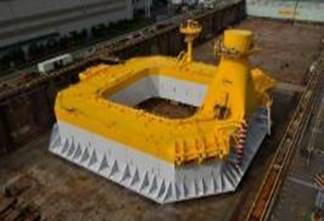
The steel barge in a dry dock Figure 3.
·
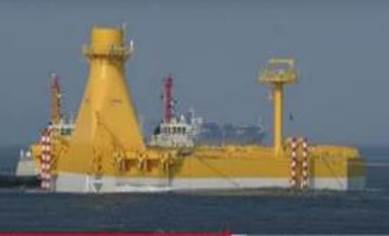
The tow to the outfitting yard, Figure 4
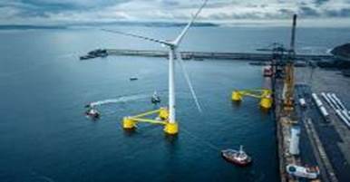
·
Nacelle installed, Figure 5
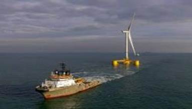
·
The tow out, Figure 6
Figure
3
|
Figure 3 Steel Barge (Credit BW-Ideol) |
Figure
4
|
Figure 4 Steel Barge Tow (Credit BW-Ideol) |
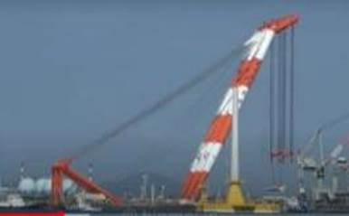
Figure 5
|
Figure 5 Lifting Blades Martini et al. (2016) (Credit BW-Ideol) |
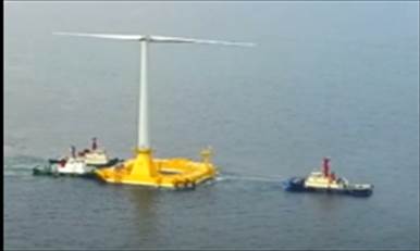
Figure 6
|
Figure 6 Steel Ring Barge Martini et al. (2016) |
A
typical sequence is shown as follows:
·
Loaded out onto a HTV Figure 7
·
Transported to the fit-out yard Figure 8
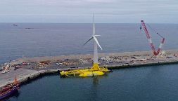
·
Nacelle installed by crane, Figure 9
·
Tow out of the structure Figure 10
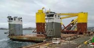
Figure
7
|
Figure 7 Load-out HTV (Credit Principle Power) |
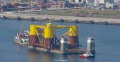
Figure 8
|
Figure 8 Dry tow (Credit Principle Power) |
Figure 9
|
Figure 9 Fit Out Quay (Credit Principle Power) |
Figure 10
|
Figure 10 Wet tow (Credit Principle Power) |
6. INSTALLATION SEQUENCE
6.1. STEEL
SEMI SUBMERSIBLE FOWT
The
installation operations are carried out with the assistance of harbour tugs,
inshore, and several AHTSs (Anchor Handling Tug and Supply) at the offshore
location. AHTSs can be used for floating wind farm work. In
particular they are used for the installation of drag anchors, tow out
of the FOWT offshore and to finally to connect the preinstalled moorings. The
floating wind industry may require new AHTS with large chain locker capacity.
The
export cable can be installed in parallel with the main structure fabrication
and installation. The marine operations for a steel Semi-submersible are:
·
The pre installation of moorings.
·
Construct, vertically, onshore
·
Load-out onto HTV, using SPMT
·
Ocean voyage HTV
·
Float-off from heavy transport vessel
·
Wet storage of substructure
·
Rotor assembly fitted with crane
·
Pre commission systems
·
Towing out to the offshore location
·
Connect the mooring and tension
·
Connect the dynamic array cable
Light
maintenance activities can be carried-out offshore.
The periodic inspections, preventive maintenance and repair activities will be
performed in situ (i.e. at the offshore wind farm). In case of large heavy
maintenance or repair activities the Semi-submersible platform can be towed to
a sheltered port Salzmann et al. (2015). However,
this requires procedures to be developed for disconnection and laydown of
mooring lines and dynamic cables. The
low draft means that there are a few ports available for fit out and for heavy
maintenance.
The
Semi-Submersible substructure has a large advantage regarding Capital
Expenditure (CAPEX because the turbine installation and commissioning can be
done in a sheltered port. The towing is straight forward due to the inherent
stability of the assembled system and the low draft. The operations needed at
sea is connecting the complete structure to pre-installed anchors. The dynamic
array cables require a specialised cable installation vessel after the moorings
have been completed.
The
anchors are with catenary mooring lines, and thus become very long and
expensive in deeper waters. In deeper water part of the chain can be replaced
by wire rope of synthetic cables.
The
turbine is usually in one corner to maximise onshore crane capacity during fit
out at a quay. The technical challenges, Lewis & Laskowicz (2023), for
floating wind structure during installation, namely:
·
Large area for the construction
·
Very wide channel needed to for tow
·
Large tug to tow offshore.
·
Large anchor handling tugs
·
Large steel content
6.2. SPAR TYPE FOWT
6.2.1. GENERAL
The
Spar substructures have large drafts which require the use of fit out in deep
water, as can be found in several Norwegian Fjords. The deep
water location also requires sheltered coastal waters. The maximum
significant wave heights are to be less than to 0.5 m, with associated wave
period less than 10 seconds, and wind speeds less than 10m/s, for inshore
lifting operations.
6.2.2. STEEL SPAR
The
marine operations for a steel spar are, Kaiser & Snyder (2011):
·
Pre installation of mooring
·
Construct steel cylinder, horizontally,
·
Load-out steel cylinder onto a HTV
·
Ocean voyage of substructure on a HTV
·
Float-off from heavy transport vessel
·
Upend with seawater ballast
·
Solid ballast added to the base
·
Seawater ballast added to increase draft
·
Tower assembled onshore with nacelle
·
Blades added onshore
·
SSCV lifts the tower assembly
·
Tower assembly bolted to substructure
·
Pre commission systems
·
Towed complete structure offshore
·
Connect the mooring lines and tension
·
Connect the dynamic array cable
6.2.3. CONCRETE SPAR
The
marine operations for a concrete spar are, Kaiser & Snyder (2011):
·
The pre installation of mooring.
·
Construct concrete partial cylinder,
·
Float partial cylinder to deep water
·
Slip form the
concrete cylinder
·
Solid ballast added to the barge
·
Add water ballast to get to required draft
·
A spacer barge on the quay
·
The tower assembly is mated by crane
·
Pre commission systems
·
Tow to the location of the wind farm.
·
Connect the mooring and tension
·
Connect the dynamic array cable
6.3. PIVOT
BUOY
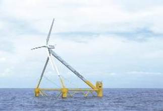
The X1 pivot buoy was built
as a semisubmersible, but is moored as a single point mooring system, Figure 11.
Figure 12 shows the demo Sath
concrete substructure with pivot buoy mooring system
Figure
11
|
Figure 11 X1 Pivot (Credit X1) |
Figure
12
|
Figure 12 Sath Pivot (Credit Sathech) |
7. RISK EVALUATION
7.1. TYPICAL
RISKS
Construction and installation risks can be identified. Thus an evaluation can be made of their safety needs and
ultimately reliability, Gerwick (2007). Each
procedure or one off operations all require full risk
evaluation. Human error often has a significant impact on construction and
installation risks and this needs to be considered in the hazard
identification. Risks which have been identified on previous wind farms
construction and installation methods include:
·
Weight control procedures
·
Delay in approvals
·
Flooding due to external damage
·
Overtopping of hull due to waves
·
Free-surface water
·
Structural cracking
·
Mooring line failure during bad weather
·
Dragging anchor
·
Explosion or fire
·
Storms such as wind, waves,
·
Acceleration loads
·
Sea-fastenings failure
·
Failure of tugs
·
Towline broken
·
Ice jamming on structure or towline
·
Excessive sway or yaw during tow
·
Large roll during tow
·
Going aground
·
Towed structure overruns tug
·
Loss of intact stability
·
Malfunction of instrumentation
·
Seafloor irregularities,
·
Excessively stiff soil or hard layers,
·
Excessively soft soils
·
Storm during installation
·
Bad visibility, fog
·
No resistance to piles driving
·
Excessive pile driving
·
Failing to float at proper draft
·
Structural damage during installation
·
Lines fouled on projecting fittings
·
Drag of anchor
·
Errors or omissions in design
To minimise accidents and errors requires training and
use of simulators.
7.2. RELIABILITY
Substructure fabrication occurs in a shipyard, which does
not need to be close to the offshore site. Conversely the fit-out yard for the
lifting of the wind turbine components needs to be within about a short tow
time of the offshore wind farm, as weather forecast are only reliable within
about 3 days. In addition the blades, nacelles and
tower need to be built at separate sites, each close to a load-out quay. Wet
storage is needed close to the fit out yard for the
substructure and for the completed structure.
The mooring equipment requires their own mobilisation
port. The moorings (anchor and chain) needs to be
installed and tensioned before the arrival of the completed floating wind
structure.
The dynamic and export cables also need specialised
factories next to a load-out quay. This is followed by ocean voyage and
installation on dedicated cable laying vessels. The export cable needs burial
in the seabed, and rock protection from potential damage from anchors or
fishing trawls.
There are many technical and commercial problems facing
the complete commercial development of floating offshore wind turbines, Blackfish (2020).
7.3. EXTREME EVENTS
Floating wind offshore turbines are subject to potential
structural collapse due to the weather forces. In addition
there also the possibility of compartment damage and partial flooding or even
sinking during tow or operation.
Designers, suppliers of equipment, fabricators and the
offshore installation companies are responsible to ensure that mechanical and
structural do not occur. Mitigation measures need to be in place to ensure that
minor failures do not propagate to complete collapse.
The construction company concerns with regards to extreme
events include, Crowle & Thies (2022):
·
Standards not complied with
·
Poor quality control
·
Tolerance on fit up exceeded
·
Poor quality welds,
·
Unapproved changes.
·
Failure to meet all specifications,
·
Lack of safety standards
·
Temporary structure collapse
Reliability and risks detailed evaluation is essential to
the selection of the preferred method for fabrication and offshore installation
of floating offshore wind turbines.
Reliability and risk evaluation is related to the
required contingency planning. Procedures thus need to be developed to prevent
accidents. Mishaps in offshore installation phase require risks to be
mitigated.
8.1. DISCUSSION
Many countries are considering the use of floating wind, Floating Offshore Wind Centre of
Excellence International Market Opportunities Summary Report (2022).
Floating wind offers the possibility of installing turbines out of sight of
land. In these deeper water the wind speed is stronger
and more consistent, Castro-Santos & Diaz-Casas
(2016). However,
as the floating turbines are constructed inshore and will be very visible to
people living close to the fit out port.
Spars of either concrete or steel construction has the
advantage of low motions during the tow out. However, the Spar substructure
requires deep water for vertical integration (fitting out) of the tower
sections, nacelle, hub, and blades. Also deep water is
required for the tow to the offshore wind farm.
The Hywind steel versions of the substructure were
constructed in Spain. They were loaded out horizontally, using trailers onto to
a heavy transport vessel (HTV). This was followed by dry ocean voyage on the
HTV before being floated off in a Norwegian Fjord. The substructure was then
upended, to the vertical, using sea water ballast before having sold ballast
placed in the base to improve intact stability. A very large semi-submersible
crane vessel was then used to fit the combined topside of tower, nacelle, and
blades. Wet storage was in a deep water fjord.
The Hywind concrete version were built vertically in a
dry dock After float-out the substructures were completed afloat using concrete
slip forming. Solid ballast was added from a rock dumping vessel, with further
sea water ballast pumped into the base to achieve the required draft. The
Topsides of tower, nacelle and blades were installed using a very large land based crane, with the assistance of a spacer barge
between the quay and the substructure.
The large steel Windfloat
Semi-submersible substructures were fabricated in a shipyard in Spain. They
were loaded out by trailer and then dry transported on a heavy transport
vessel. The substructures were floated off in Rotterdam close to the vertical
integration quay. Fit out, vertical
integration, of tower sections, nacelle, hub, and blades took place with the
substructure moored on a quay using a large onshore crane.
The ring barge by BW-Ideol has
been deployed as a demonstration in steel and concrete versions. Outfit was
done using large land based cranes being operated on
the fit-out quay.
8.2. CONCLUSIONS
Several ports are needed for the fabrication and offshore installation
of floating wind turbines:
·
Shipyard for substructure fabrication
·
Quays for nacelle, towers, and blades
·
Marshalling port for anchors and chains
·
Factory for the export power cables
·
Vertical integration port for topside
Schedule and cost of construction can be reduced by:
·
Planning components flow
·
Storage on the fit out quay
·
Details are to be Standardized
·
Tight tolerances to be avoided
·
Smooth labour force requirements
· Minimise weather down tine.
9. Terminology
|
TERM |
DEFINITION |
|
CAPEX |
Capital expenditure |
|
FOWT |
Floating offshore
wind turbine |
|
GW |
Giga watt |
|
HTV |
Heavy transport
vessel |
|
HVAC |
High voltage
alternating current |
|
HVDC |
High voltage direct
current |
|
LCOE |
Life
time cost of energy |
|
Kv |
kilovolt |
|
M |
metre |
|
MW |
Mega watt |
|
MWS |
Marine warranty
surveyor |
|
QA |
Quality assurance |
|
QC |
Quality control |
|
SPMT |
Self propelled modular transporter |
|
SSCV |
Semi
submersible
crane vessel |
CONFLICT OF INTERESTS
None.
ACKNOWLEDGMENTS
Alan Crowle thanks his colleagues at the University of Exeter for their assistance in preparing this paper. However, the paper represents the opinion and views of the author, and does not necessarily represent those of University of Exeter. Alan Crowle wishes to thank in particular Professor P.R Thies.
REFERENCES
Blackfish (2020). Floating Offshore Wind, Installation Challenges, Operations and Maintenance.
Castro-Santos, L., & Diaz-Casas, V. (2016). Floating Offshore Wind Farms. https://doi.org/10.1007/978-3-319-27972-5.
Choisnet, T., Vasseur, S., & Rogier, E. (2018). Performance and Mooring Qualification in Floatgen : The First French Offshore Wind Turbine Project,Ideol SA, La Ciotat, France.
Construction Vessel Guideline for the Offshore Renewables Industry, Energy Institute (2014, September).
Crowle, A.P., & Thies, P.R. (2022, November 8th). Naval Architecture Methods For Floating Wind Turbine Installation. International Conference on Postgraduate Research in Maritime Technology, The Confederation of European Maritime Technology Societies (CEMT).
Crowle, A.P., & Thies, P.R. (2022). Floating offshore Wind Turbine - Heavy Construction Requirements, Trends in Renewable Energies Offshore - Proceedings of the 5th International Conference on Renewable Energies Offshore, RENEW 2022, 639-649. https://doi.org/10.1201/9781003360773-72
Efthimiou, L., & Mehta, A., (2022). Crash Course - Floating offshore Wind a Blog Series (Part 2), World Forum Offshore Wind.
Floating Offshore Wind Centre Of Excellence International Market Opportunities Summary Report (2022, May).
Gerwick, B. (2007). Construction of Marine and Offshore Structures, (3rd Ed.). https://doi.org/10.1201/9781420004571
Kaiser, M.J., & Snyder, B. (2011). Offshore Wind Energy Installation and Decommissioning Cost Estimation in the U.S. Outer Continental Shelf, Technical Report, US Dept. Of the Interior, Bureau of Ocean Energy Management, Regulation and Enforcement, Herndon. VA TA&R Study, 648, 340.
Ksenia Balanda et al (2022). The Role of the Local Supply Chain in the Development of Floating Offshore Wind Power. IOP Conference Series: Earth and Environmental Science.
Lewis, P., & Laskowicz, T. (2023). Intelatus Global Partners, UK), Evolving Requirement For Floating Wind Installation Vessels, RINA-ABS Offshore Conference Aberdeen 2023.
Martini, M., Jurado, A., Guanche, R., & Losada, I. J. (2016). Evaluation of Walk-To-Work Accessibility for a Floating Wind Turbine. International Conference on Offshore Mechanics and Arctic Engineering. https://doi.org/10.1115/OMAE2016-54416
Ojo, A., Collu, M., & Coraddu, A. (2022). Multidisciplinary Design Analysis and Optimisation of Floating Turbine Structures: A Review, Ocean Engineering. https://doi.org/10.1016/j.oceaneng.2022.112727
Olsen, F., & Dyre, K. (1993). VIndeby Off-Shore Wind Farm-Construction and Operation. Wind Engineering, 17(3), 120-128.
Ramachandran, R., Desmond, C., Judge, F., Serraris, J., & Murphy, J. (2022). Floating Wind Turbines: Marine Operations Challenges and Opportunities, EAWE.
Salzmann, D. C., Prezzi, J., Ten Haaf, S., & Groenteman, S. (2015). Walk to Work Offshore Using Motion Compensated Gangways, in: OTC Brasil, OnePetro, https://doi.org/10.4043/26197-MS
Santos, F. P., Teixeira, Â. P., & Soares, C. G. (2016). Operation and Maintenance of Floating Offshore Wind Turbines, in: Floating Offshore Wind Farms, Springer, 181-193, https://doi.org/10.1007/978-3-319-27972-5_10
Shu, Y. (2022). Research on Prevent Failure and Key Technologies to Install Jib of Large Floating Crane. Australian Journal of Mechanical Engineering. https://doi.org/10.1080/14484846.2022.2108580
Tremblay, M. (2021, October). New Insight into U.S. Regulations for Offshore Wind Vessels, North American Clean Energy, 15(5).
 This work is licensed under a: Creative Commons Attribution 4.0 International License
© Granthaalayah 2014-2024. All Rights Reserved.