TECHNICAL ARCHIVES AND CLASSIFICATION OF DOCUMENTS: AN APPLICATION MODEL FOR GRAPHIC MATERIAL
Silvano Tozzo 1![]()
![]()
1 Politecnico di Milano, Milano, Italy
|
|
|
ABSTRACT |
|
|
From the literature on the archives, it is possible to perceive different solicitations relative to an instrument, the classification, whose purpose, among others, is to simplify the recognition of the graphic material preserved within a Fund. Generally, a drawing presents distinctive peculiarities in reference to what comes depicted from it to the type of representation to which it appertains, to the purpose that it must achieve. Moreover, of course, all these aspects contribute to determining the class to which it belongs within a reorganization process related to documents produced by construction activities. Therefore, the
following exposition presents the methods and theoretical instruments used to
treat information extracted from technical and project drawings. |
|||
|
Received 01 July 2023 Accepted 02 August
2023 Published 16 August 2023 Corresponding Author Silvano
Tozzo, silvano.tozzo@polimi.it DOI 10.29121/granthaalayah.v11.i7.2023.5246 Funding: This research
received no specific grant from any funding agency in the public, commercial,
or not-for-profit sectors. Copyright: © 2023 The
Author(s). This work is licensed under a Creative Commons
Attribution 4.0 International License. With the
license CC-BY, authors retain the copyright, allowing anyone to download,
reuse, re-print, modify, distribute, and/or copy their contribution. The work
must be properly attributed to its author.
|
|||
|
Keywords: Archives, Classification, Drawings |
|||
1. INTRODUCTION
The
analysis and evaluation regarding a set of technical and project drawings – a
significant part of a Fund[1] consisting of material of a different nature – become actions aimed at a
better comprehension of the documental complex to which they belong. The
process of extrapolation and computerisation of data[2]
obtained from graphic material promotes major attention to those different characteristics
findable in the drawings. Characteristics connected to
their role within the technical and project process, to the quality of the
graphic representation, and to their transformation from functional instruments
to cultural heritage. Alisio et al. (1994)
The
graphic representations from the construction sector express different
qualitative and typological levels if contextualised in their content. Drawings that photograph sections of buildings and belong
to the classic repertoire of the architectural project (plans, fronts, views),
technical representations relating to elements in detail, to implants in
general (electrical and hydraulic schemes), and to technological
instrumentation of service. What has just been affirmed prefigures, during
the classification, discreet attention to the peculiarities of each graphic
model, namely a certain adherence in the transformation phase into computer
data to those visible characteristics that each drawing expresses and
communicates through the various forms in which it manifests itself. Antuono (1990)
The
following sections will expose, with the help of examples, the system used
addressed to a rational organisation of the data extracted from the graphic
material to obtain a feasible identification and relative reading of what is
preserved in the archive. Carpeggiani & Patetta
(1989)
2. MODALITY OF DATA ORGANIZATION DERIVING FROM GRAPHIC MATERIAL
The
organisation of the data obtained from the graphic material is exposed as
follows, taking the schematisation reported in Table 1 as the main reference.
Through
this tool, the presentation considers an exhibition itinerary connected to the functionality
of sectors (database spaces[3]).
It means that these fields are described mainly in relation to the quality of
their content and secondarily regarding the numerical consequentiality
highlighted in the scheme just mentioned. The setting modalities of data are
made visible with the help of tables and appendices through which to verify
what was expressed in the narration dedicated to them. Corti (1999)
Table 1
|
Table 1 Fields and Relative Content |
||
|
FIELD |
CAPTION |
CONTENT |
|
ID |
PROGRESSIVE NUMBER |
A sequential number assigned to the
Record in which the data acquired from the drawing is inserted |
|
1 |
CAMPUS ACRONYM |
Abbreviation derived from the
location/campus where the technical intervention that produced the drawing
was performed. |
|
2 |
TECHNICAL INTERVENTION |
Brief definition of the technical
operation from which the graphic material comes |
|
3 |
LOCALIZATION 1 |
Building/Unit/Structure affected by the
intervention that has produced the drawing. |
|
4 |
LOCALIZATION 2 |
City/Campus/Area affected by the
intervention that has produced the drawing. |
|
5 |
FOLDER CODE |
Code assigned to the folder containing
the graphic material |
|
6 |
DOCUMENT TYPE |
Typology to which the drawing belongs |
|
7 |
DOCUMENT CLASS |
Class to which the graphic material belongs |
|
8 |
IDENTIFICATION CODE |
Drawing code |
|
9 |
DESCRIPTION |
|
|
10 |
VARIABLE DATA |
Data relating to drawing |
|
11 |
DATE |
Production date of drawing |
|
12 |
YEAR |
Production year of drawing |
|
13 |
DOCUMENT PRODUCTION Indication 1 |
First subject (Institution, Company,
etc.) involved in drawing formation |
|
14 |
VARIABLE DATA |
Data relating to drawing |
|
15 |
DOCUMENT PRODUCTION Indication 2 |
Second subject (Institution, Company,
etc.) involved in drawing formation |
|
16 |
COLLOCATION |
Cabinet in which the drawing is placed |
|
17 |
POSITIONING |
Code relating to the position of the
drawing |
Following what has been affirmed above, it is proper to start with the
interpretation of database spaces. The comprehension relating to localisation connected to the graphic
material affects Fields 1, 3, and 4. Therefore, its
geographical association inasmuch produced (the graphic material) by technical
operations effectuated in structures and areas included in the university’s
territorial network. The
information legible in the three fields is closely linked because it visualises
the working context (site, area) from which the drawings are generated.
Field 1
regards the city/district dimension synthesised through an abbreviation of
three letters. Fields 3 and 4 highlight the specific references of the
technical intervention from which the graphic material comes. While the content in these spaces (3-4) regards the minor
situation, quite variable (classroom, building), the acronym (field 1) identifying the
territorial pole establishes a geographical division concerning the actions
effectuated within the single urban campus; the division interest the organisation
of data acquired from the retained drawings. De Simone (1990)
The three
spaces mentioned, detectable in Table 1, are exemplified through the data
displayed in Masks A and B (Appendix 1 and Appendix 2). Mask A refers to a planimetry
performed within an operation related to the maintenance of electrical systems.
In this case, the university seat involved is within the city of Como, and therefore,
the abbreviation COM is legible in Field 1, representing the territorial seat
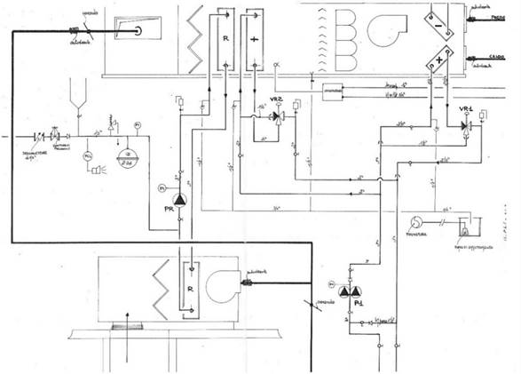
in which the technical operation has been completed. Mask B proposes a scheme (Figure 1) realised within a maintenance
intervention of mechanical implants. The drawing is part of the document group
attributable to the intervention: Department
of Electronics. General maintenance of mechanical implants, a department
located in the district called City of Studies (Milano), abridged in Field 1
with the acronym CIS. Thus, the indications referring
to the localisation – this one is divided into two territorial scale levels,
the lower one in Field 3, and the upper one in 4 – display in Masks A and B,
the two areas (Anzani and Bassini)
affected by the interventions and inserted respectively in the university
settlements of Como and Milano; these latter are visible in Field 4 as higher
level indicators Del Monaco & Re (1986)
Figure 1
|
Figure 1 Mechanical Scheme |
The
examples just mentioned underline the meaning relating to the order of the
territorial scale of what is reported in the two fields. As it is easy to
imagine, it passes by drawings resulting from project proposals involving
areas/buildings to realisations connected to simple maintenance regarding minor
situations in classrooms and offices. In any case, graphic material referring
to major or minor interventions has in common the prerogative of being
connected to the physical place where the technical operation that generated it
was performed. Therefore, the geographical and
localisation framing of data originating from drawings makes available a more
complete information. Guillerme (1982)
It is now
plausible to proceed with the narration relating to the other sectors of the
database in which to find the data concerning the graphic representations.
The text
visible in Fields 2–9 is of a descriptive nature and relates to the general
definition of the document grouping to which the graphic material belongs
(Space 2) and the specific one relative to its content (Space 9). The following
example is useful for verifying the type of information associated with the two
situations now cited. Massironi (1989)
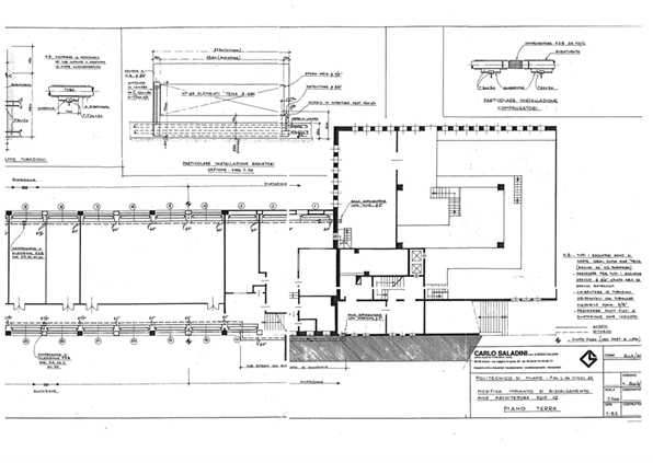
The
drawing (Figure 2), whose data are evident in Appendix
3 (Mask C), displays an implant
schematically represented in the plan of a building. Space 2 reports the
definition concerning the technical intervention that has produced the graphic
work cited as an example, namely School
of Architecture: Heating system. The document series with this description
collects 12 pieces, including the scheme presented above. The remainder of a
limited number of elements is probably due to the time passage and other
reasons, because this intervention belongs to a typology that usually releases
a fair amount of graphic and administrative material.
Every
project action may include a very variable quantity of documents. This depends
on the consistency of the intervention from which they are produced, and
obviously, all the drawings resulting from the same operation will report an
equal definition in Field 2. The utility of this common denominator resides in
the possibility of identifying the document situation in which the drawing, the
object of attention, is inserted. Therefore, the consequent simplification
relative to the single element position and its connection to other documents,
conceived by the same work but placed in different folders. Mezzanotte & Mazzotta Buratti (1980)
Figure 2
|
Figure 2 School of Architecture. Heating System. Plan-Details-Section (1:100) |
The
description relating to the content of the graphic material is inserted in
Space 9. The text may differ in terms of extension, as the drawings present
themselves in diverse expressive forms. The redaction
modalities of a plan or planimetry assume proper characteristics as a consequence, for example, of the dimensional scale and
the level of detail used. Thus, the text used – to describe these aspects and
peculiarities of other type visible within the graphic part – can be synthetic
or more dilated in compliance with the features of the drawing.
Reviewing the content exhibited in Mask C (Appendix 3) – used before for the evidence of
Field 2 – it is possible to ascertain an essential description of the drawing
in Space 9 (Figure 2). In the graphic part outside the
plan, details of the implant are visible as, in effect, reported in the text,
while its structure inside the building plan is well represented. The presence
of some technical annotations, in this case, legible above the title block, is
a particular that is sometimes visible in the drawings depicting implants or
technological instrumentation. Ministry of Cultural and
Environmental Heritage (1999)
Continuing
in the manifestation of the organisational modalities of data extracted from graphic
material and, therefore, maintaining the schematisation proposed in Table 1 as a directional instrument, it is
now possible to verify the quality of the content present in Fields 5 and
16–17. The information legible in these three spaces is aimed at the physical
identification of the drawings. Field 5 highlights the container through the
code assigned to it; this abbreviation is obtained from the definition
attributed to the material[4]
produced by the technical intervention and preserved in the folder. Field 16
contains the indication regarding the cabinet in which the folder resides and,
finally, Field 17, in which the sequence (alphanumeric) relative to the
collocation of the single element is legible.
The
example presented below serves to visualise the three options cited and
highlight the relational dimension existing between them and connected to the
information present in the other fields. Patetta (2009)
The
drawing, whose data are readable in Appendix
4 (Mask D), has been generated by the
intervention defined: Bookshop CLUP.
Emergency exits, effectuated in 1984, of which have remained four pieces.
The graphic representation exhibits the plan, the front and the section of the
edifice fraction affected by the project; the minor binder in which it is
inserted is part of the folder INV12 containing 13 dossiers for 136 pieces.
Therefore, the code assigned to the folder in which the drawing just displayed
is placed is shown in Space 5; obviously, it allows its identification inside
the cabinet where it is collocated. The cabinet
identification, legible in Space 16, comes about by letters/numbers affixed to
its opening/closing doors. The two alphanumeric combinations – the first
necessary to recognise the folder containing the graphic material and the
second to identify the cabinet in which it is placed – are included in the
final sequence, relating to the physical position of the drawings reported in
Field 17. In this space , always referring to the data shown in Mask D, the
sequence assigned to the drawing is as follows: A.INV12.DS28021984/748, where A
identifies the cabinet, INV12 is the folder, DS is the abbreviated category as
visible in Table 2, 28021984 is the date without
separators [5] ,
and 748 is the number assigned to the internal dossier containing the material
relative to the intervention described in Space 2. Piva & Galliani (2005)
It is
probably easy to imagine the usefulness of a classification system in the
presence of a discreet concentration of graphic material produced from
activities related to the construction sector.
The
different characteristics detectable in terms of functional, aesthetic,
dimensional scale, and type of representation suggest the formation of an
instrument through which to assign classes that consider these peculiarities.
Table 2
|
Table 2 Categories of Graphic Material |
|
|
Graphic
Material (cartography) |
Code |
|
DRAWING
(DISEGNO) |
DS |
|
FRONT
(PROSPETTO) |
PR |
|
PICTURE
(IMMAGINE) |
IM |
|
PLAN
(PIANTA) |
PT |
|
PLANIMETRY
(PLANIMETRIA) |
PL |
|
SCHEME
(SCHEMA) |
SC |
|
SECTION
(SEZIONE) |
SE |
|
VIEW
(VISTA) |
VS |
Table 2 reports the categories attributed
to the graphic material with the relative abbreviations utilised for forming
the collocation code legible in Space 17 (Table 1), as seen in the example just
shown. Poggiali & Bigi (1983)
The
database fields, where the classes in which the graphic material is divided,
are Fields 6 and 7 (Table 1), as perceptible in the record
visualised in Appendix
5 (Mask E). Field six is useful to
differentiate the graphic material from the common documents [6]
and the seven to classify it based on the representation type adopted (Front,
Plan, etc.). The data, legible in Mask E, have been taken from the drawing of
an air conditioning system (Figure 3). The graphic part resumes the
scheme, and two details of the implant are described in the title block as a
plan of the air conditioning system. Considering the characteristics, what is
reported in the description, and the presence of different expressive styles
(plan-scheme-section), the graphic illustration has been assigned to the
generic class Drawing [7]. Sometimes this type of
representation is shown in the edifice plan; in this case, the implant scheme
is graphically isolated from the referencing context. Ratto & Calloni
(1965)
Figure 3
|
Figure 3 Detail of the Air Conditioning System |
After having seen the content of Fields 6–7 regarding the division of
the graphic material into classes, this exposition continues – always
considering Table 1 – with the interpretation of data
entered in the spaces not yet examined.
The
information legible in the lower band of the drawing – preferably on the right
side in the space occupied by the title block – comes exhibited in Fields 8,
11–12, and 13–15 of the database. In the example manifested in Appendix 6 (Mask F), it is possible to verify
what is affirmed. The electrical scheme proposed in the visualisation belongs
to the document grouping with the definition: Diverse works relating to electrical systems and substations. This
last definition is used for material contained in five folders and, therefore,
derives from a consistent intervention. The data obtained from the title block,
as mentioned above, complete the spaces specified before and regard the number
or alphanumeric code assigned to the drawing, the date and year of production,
and the indications about the subjects involved in their execution. Returning
to data visible in Mask F concerning an electric scheme, it is possible to
ascertain the content of the spaces previously mentioned. Space 8 shows the
identification code, in this case, present and assigned to the drawing as
follows: 462/C1[8]; Date and year are legible, respectively, in fields 11 and
12 [9]; the producer of this one, the
technical department, is visible in Space 13 as the only indication reported in
the title block [10].
The final
part of this writing concerns the information relative to Fields 10–14,
characterised by a certain variability in terms of content. This is because the
data perceptible in these spaces assume – as shown in the examples presented
below – a dimension useful but probably less significant compared to what was
reported in other parts of the database. Rovida (1999)
In Appendix
1, Appendix 2, Appendix
3, Appendix
4 and Appendix 6, the attributions relative to
Spaces 10 and 14 are visible. The quality of the
information detectable from them and labelled with the definition variable
data, as observable in the already cited Table 1. In effect, their prerogative is to complete,
with additional details of a different nature, the information framework
connected to the graphic material in the classification phase. The drawings
presented in the masks, through their data and their characteristics, also
become useful for a synthetic and quick analysis relating to the content of Fields
10–14. The type of data may concern the dimension scale of the graphic
representations (Masks A, D, and E), the number of the internal dossier in
which the drawing is inserted (Masks C–D), and a technical specification
relating to an electrical system (Mask F).
The
situations just highlighted conclude the exposition relating to the modalities
of setting the data obtained from the drawings. The different cases presented
through the text, appendices, and images are aimed at the comprehension of the
conceptual system used and an aware reading of the information detected from
the graphic material and translated into computer data. Vetriani & Morabito (1984)
3. FINAL CONSIDERATIONS
The model exposed in this paper – with the assistance of tables,
appendices, and figures to support the text – in addition to the classification
system, highlights, through the reading of
data, the relational intertwining perceptible in the recognition of the
document aggregation to which the drawings refer.
The
visibility of data – reported through masks [11]
presented for this purpose – contributes to increasing knowledge relative to
specific technical situations and allows the retrieval of material potentially
useful to support maintenance and project operations in the various areas and
structures involved.
In closing, the last annotation concerns the cultural dimension acquired by the drawings with the time passage. The verification of the graphic material produced in the past for different motives becomes interesting, among which are the historical research connected to the evolution of the technical instrumentation and the aesthetic value recognisable in representations performed manually. Those just mentioned are only some of the reasons for which the preservation and enhancement of graphic material remain practicable options in the presence of a discreet concentration of pieces detectable in a technical archive.
CONFLICT OF INTERESTS
None.
ACKNOWLEDGMENTS
None.
REFERENCES
Alisio, G., Cantone, G., De Seta, C., and Scalvini, M.L. (1994). The Archive Drawings in
Architecture History Studies
(I Disegni d’archivio Negli Studi di Storia dell’ Architettura), Conference Proceedings, Italy, June 12-14, 1991, Electa.
Antuono, W. (1990). Technology,
Drawing and Project (Tecnologia,
Disegno e Progettazione) Marigliano : Italibri.
Carpeggiani, P., & Patetta, L. (1989). The Drawing of Architecture (Il Disegno di Architettura), Milano
: Guerini.
Corti, L. (1999). Cultural Heritage and Their
Cataloguing (I Beni Culturali
e La Loro Catalogazione), Torino : Paravia.
De Simone, M. (1990). Drawing, Measuring,
Project : the Drawing of Ideas,
the Project of Things (Disegno,
Rilievo, Progetto : Il Disegno Delle Idee, il Progetto Delle Cose), Roma : NIS.
Del Monaco, G. & Re, V. (1986). Electrotechnical and Electromechanical
Drawing (Disegno Elettrotecnico ed Elettromeccanico), Milano : Delfino.
Guillerme, J. (1982). The Figuration in Architecture
(La Figurazione in Architettura),
Milano : Franco Angeli.
Massironi, M. (1989). See with Drawing : Technical, Cognitive, Communicative Aspects (Vedere Con Il Disegno : Aspetti Tecnici, Cognitivi, Comunicativi). Padova : Muzzio.
Mezzanotte, G., Mazzotta Buratti,
A.C. (1980). Drawing Anthology for a Methodical of the
Study and for a History of
Project Drawing (Antologia Del
Disegno. Per Una Metodica Dello Studio E Per Una Storia Del
Disegno Di Progetto),
Milano : CLUP.
Ministry of Cultural and Environmental Heritage (1999). Archives for the History of Science and Technology (Gli Archivi Per La Storia Della Scienza E Della Tecnica), Roma : Tipografia della pace.
Patetta, L. (2009). Writings
on Architectural Drawing (Scritti
sul disegno di architettura), Milano : Libraccio.
Piva, A., & Galliani,
P. (2005). The Archives of the Project (Gli Archivi Del Progetto), Milano : Lybra.
Poggiali, G., & Bigi, G. (1983). Technical Drawing
Elements : Principles and Design of Machines (Elementi Di Disegno Tecnico : Principi E Disegno Di Macchine) Bologna : Zanichelli.
Ratto, G., & Calloni, G. (1965). Reading and Interpretation of the Technical Drawing (Lettura ed Interpretazione
Del Disegno Tecnico) Bergamo : Editrice
San Marco.
Rovida, E. (1999). From Chisel to Mouse.
Evolution and History of Technical
Drawing (Dallo Scalpello al Mouse Evoluzione e Storia Del Disegno Tecnico), Torino : Paravia.
Vetriani, G., & Morabito, G. (1984). The Coordination of Project Documentation Through
the Use of a Classification System (Il Coordinamento
Della Documentazione Progettuale
Mediante l'uso di un Sistema di Classificazione), Conference Proceedings, Italy, October 22, 1983, La Sapienza.
APPENDIX
Appendix 1
|
Appendix 1 MASK A |
||
|
PROGRESSIVE NUMBER |
671 |
|
|
1 |
CAMPUS
ACRONYM |
COM |
|
2 |
TECHNICAL
INTERVENTION |
Regional pole of Como. Realization of low
voltage three-phase line and new electrical substation |
|
3 |
LOCALIZATION
1 |
ANZANI |
|
4 |
LOCALIZATION
2 |
COMO |
|
5 |
FOLDER
CODE |
COM/A |
|
6 |
DOCUMENT
TYPE |
CARTOGRAPHY |
|
7 |
DOCUMENT
CLASS |
PLANIMETRY |
|
8 |
IDENTIFICATION
CODE |
SI01.0/0 |
|
9 |
DESCRIPTION |
Safety and coordination plan. Current status. General planimetry |
|
10 |
VARIABLE
DATA |
1:2000 |
|
11 |
DATE |
01/06/2004 |
|
12 |
YEAR |
2004 |
|
13 |
DOCUMENT
PRODUCTION Indication
1 |
Technical Department |
|
14 |
VARIABLE
DATA |
* |
|
15 |
DOCUMENT
PRODUCTION Indication
2 |
* |
|
16 |
COLLOCATION
|
CABINET D6 |
|
17 |
POSITIONING |
D6.PRC/A. PLSI0100 |
Appendix 2
|
Appendix 2 MASK B |
||
|
ID |
PROGRESSIVE
NUMBER |
8725 |
|
1 |
CAMPUS
ACRONYM |
CIS |
|
2 |
TECHNICAL
INTERVENTION |
Department of Electronics. General
maintenance of mechanical implants |
|
3 |
LOCALIZATION
1 |
EDIFICE 18 |
|
4 |
LOCALIZATION
2 |
BASSINI |
|
5 |
FOLDER
CODE |
DEL24 |
|
6 |
DOCUMENT
TYPE |
CARTOGRAPHY |
|
7 |
DOCUMENT
CLASS |
SCHEME |
|
8 |
IDENTIFICATION
CODE |
153PLT32 |
|
9 |
DESCRIPTION |
Edifice 18-Air conditioning system.
Mechanical scheme |
|
10 |
VARIABLE
DATA |
* |
|
11 |
DATE |
07/06/95 |
|
12 |
YEAR |
1995 |
|
13 |
DOCUMENT
PRODUCTION Indication
1 |
SPRING civil engineering |
|
14 |
VARIABLE
DATA |
* |
|
15 |
DOCUMENT
PRODUCTION Indication
2 |
* |
|
16 |
COLLOCATION
|
CABINET AA |
|
17 |
POSITIONING |
AA. DEL24.153PLT32 |
Appendix 3
|
Appendix 3 MASK C |
||
|
ID |
PROGRESSIVE NUMBER |
8713 |
|
1 |
CAMPUS ACRONYM |
CIS |
|
2 |
TECHNICAL INTERVENTION |
School of Architecture. Heating system |
|
3 |
LOCALIZATION 1 |
EDIFICE 12 |
|
4 |
LOCALIZATION 2 |
BONARDI |
|
5 |
FOLDER CODE |
INV12 |
|
6 |
DOCUMENT TYPE |
CARTOGRAPHY |
|
7 |
DOCUMENT CLASS |
PLAN |
|
8 |
IDENTIFICATION CODE |
803/1 |
|
9 |
DESCRIPTION |
Classrooms Building 12 ground floor.
Implant modification. Plan-details-section (1:100) |
|
10 |
VARIABLE DATA |
Annex to communication 803/85 |
|
11 |
DATE |
00/03/1985 |
|
12 |
YEAR |
1985 |
|
13 |
DOCUMENT PRODUCTION Indication 1 |
SALADINI SAS |
|
14 |
VARIABLE DATA |
Internal folder 753 |
|
15 |
DOCUMENT PRODUCTION Indication 2 |
* |
|
16 |
COLLOCATION |
CABINET A |
|
17 |
POSITIONING |
A. INV12.DS8031/753 |
Appendix 4
|
Appendix 4 MASK D |
||
|
ID |
PROGRESSIVE NUMBER |
8704 |
|
1 |
CAMPUS ACRONYM |
CIS |
|
2 |
TECHNICAL INTERVENTION |
CLUP University Bookshop. Emergency exits |
|
3 |
LOCALIZATION 1 |
EDIFICE 2 |
|
4 |
LOCALIZATION 2 |
LEONARDO |
|
5 |
FOLDER CODE |
INV12 |
|
6 |
DOCUMENT TYPE |
CARTOGRAPHY |
|
7 |
DOCUMENT CLASS |
DRAWING |
|
8 |
IDENTIFICATION CODE |
28021984 |
|
9 |
DESCRIPTION |
CLUP University Bookshop -Project.
Plan/Front/Section |
|
10 |
VARIABLE DATA |
1:50 |
|
11 |
DATE |
28/02/84 |
|
12 |
YEAR |
1984 |
|
13 |
DOCUMENT PRODUCTION Indication 1 |
Technical Department |
|
14 |
VARIABLE DATA |
Internal folder 748 |
|
15 |
DOCUMENT PRODUCTION Indication 2 |
* |
|
16 |
COLLOCATION |
CABINET A |
|
17 |
POSITIONING |
A. INV12.DS28021984/748 |
Appendix 5
|
Appendix 5 MASK E |
||
|
ID |
PROGRESSIVE NUMBER |
8726 |
|
1 |
CAMPUS ACRONYM |
CIS |
|
2 |
TECHNICAL INTERVENTION |
Department of Electronics. General
maintenance of mechanical implants |
|
3 |
LOCALIZATION 1 |
EDIFICE 18 |
|
4 |
LOCALIZATION 2 |
BASSINI |
|
5 |
FOLDER CODE |
DEL24 |
|
6 |
DOCUMENT TYPE |
CARTOGRAPHY |
|
7 |
DOCUMENT CLASS |
DRAWING |
|
8 |
IDENTIFICATION CODE |
153PLT34 |
|
9 |
DESCRIPTION |
E18-Air-conditioning system. Scheme input
ducts |
|
10 |
VARIABLE DATA |
1:50 |
|
11 |
DATE |
07/06/95 |
|
12 |
YEAR |
1995 |
|
13 |
DOCUMENT PRODUCTION Indication 1 |
SPRING civil engineering |
|
14 |
VARIABLE DATA |
* |
|
15 |
DOCUMENT PRODUCTION Indication 2 |
* |
|
16 |
COLLOCATION |
CABINET AA |
|
17 |
POSITIONING |
AA. DEL24.153PLT34 |
Appendix 6
|
Appendix 6 MASK F |
||
|
ID |
PROGRESSIVE NUMBER |
8010 |
|
1 |
CAMPUS ACRONYM |
CIS |
|
2 |
TECHNICAL INTERVENTION |
Diverse works relating to electrical
systems and substations |
|
3 |
LOCALIZATION 1 |
ELECTRICAL SUBSTATIONS |
|
4 |
LOCALIZATION 2 |
CITY OF STUDIES DISTRICT |
|
5 |
FOLDER CODE |
ELE4 |
|
6 |
DOCUMENT TYPE |
CARTOGRAPHY |
|
7 |
DOCUMENT CLASS |
SCHEME |
|
8 |
IDENTIFICATION CODE |
462/C1 |
|
9 |
DESCRIPTION |
Electrical substation 1. Power scheme and
addresses of telecontrol |
|
10 |
VARIABLE DATA |
New electrical implant at medium voltage |
|
11 |
DATE |
00/10/1983 |
|
12 |
YEAR |
1983 |
|
13 |
DOCUMENT PRODUCTION Indication 1 |
Technical Department |
|
14 |
VARIABLE DATA |
* |
|
15 |
DOCUMENT PRODUCTION Indication 2 |
* |
|
16 |
COLLOCATION |
CABINET A |
|
17 |
POSITIONING |
A. ELE4.SC462C1 |
[1] Construction archive of Politecnico di
Milano
[2] The data have been inserted into a Microsoft Access database.
[3] The terms space and field assume identical meaning. They are utilised
alternately to avoid the repetition of the same word
[4] It refers to the definition of documental grouping visible in Space 2
[5] In the absence of the identification elements of the graphic
representation (drawing number), the date is utilised in numerical sequence
without separators in Spaces 8 and 17, as in this case.
[6] The Archive in which the graphic material is preserved, also contains
text documents (reports, correspondence, etc.). It has been therefore necessary
to adopt a first level of classification to separate the graphic
representations from textual material.
[7] The generic class, drawing, is assigned to an elaborate in which the
representation object comes displayed through different expressive types (plan,
front, section).
[8] This kind of data is not always visible in graphic material. In the
absence of any recognisable element, Space 8 uses present alternatives legible
in the title block (date, year, letters/numbers taken from the description of
the drawing).
[9] Sometimes comes omitted the creation day of drawing with the
restitution of the indications relating to month and year, or only this last
one. To cope with the absence of a specific date, usually legible in the title
block, the spaces related to time references are two to insert in Space 12, in
similar cases, the only indication of the drawing production year.
[10] Often, there are two references (not in this case) related to the
production of drawing in the title block. Usually, the two entities specified
are the technical office and the company that has realised what is represented
(implant, equipment). Therefore, the formation of two spaces (13–15) has
consented to report the options legible relative to the subjects involved.
[11] The Mask is an MS Access software tool that allows the display of
data entered in the database.
 This work is licensed under a: Creative Commons Attribution 4.0 International License
© Granthaalayah 2014-2023. All Rights Reserved.