Design and Implementation of Band-Pass Filters for the 5th Generation Wireless System
Chung-Long Pan 1![]() , Chun-Hsu Shen 2
, Chun-Hsu Shen 2![]() , Wei-Chen Lin 3
, Wei-Chen Lin 3![]() , Ping-Cheng Chen 4
, Ping-Cheng Chen 4![]()
1 Department
of Electrical Engineering, I–Shou University, No.1, Sec. 1, Syuecheng
Rd., Dashu District, Kaohsiung City 84001, Taiwan,
China
2 Department
of Electronic Engineering, Ming Chuan University, 5 De Ming Rd., Gui Shan
District, Taoyuan City 33348, Taiwan, China
3 Medical Research Department, E-DA
Hospital, Kaohsiung 82445, Taiwan, China
4 Department of Intelligent Network
Technology, I–Shou University, No.1, Sec. 1, Syuecheng
Rd., Dashu District, Kaohsiung City 84001, Taiwan,
China
|
|
|
ABSTRACT |
|
|
This paper
proposes a band-pass filter with a center frequency of 4.2 GHz, which can be
applied in fifth - generation (5G) mobile communication. Currently, 5G
networks are experiencing rapid development and are highly regarded as the primary
network technology. Currently, 5G technology can be divided into two major
frequency ranges. The first range is defined by 3GPP and operates below 6
GHz, known as the sub-6 GHz frequency range. The second range falls
approximately between 30 GHz and 100 GHz. This paper aims to design a
microstrip band-pass filter with a center frequency of 4.2 GHz. By modifying
the line width, shape, and the number of couplings in the filter, we can
achieve the desired frequency range and increase the bandwidth. A 4.2 GHz
bandpass filter was fabricated on an FR4 substrate with a relative dielectric
constant of 4.4, and the overall dimensions is 17×5×1.55 mm3.and measured. T
Through simulation analysis, it can be understood that adding the inner ring
with a gap can improve the overall performance of the filter. |
|||
|
Received 19 May 2023 Accepted 20 June 2023 Published 05 July 2023 Corresponding Author Ping-Cheng
Chen, chen1113@isu.edu.tw DOI 10.29121/granthaalayah.v11.i6.2023.5211 Funding: This research
received no specific grant from any funding agency in the public, commercial,
or not-for-profit sectors. Copyright: © 2023 The
Author(s). This work is licensed under a Creative Commons
Attribution 4.0 International License. With the
license CC-BY, authors retain the copyright, allowing anyone to download,
reuse, re-print, modify, distribute, and/or copy their contribution. The work
must be properly attributed to its author.
|
|||
|
Keywords: Open-Loop Resonator, Band-Pass Filter, Sub-6G |
|||
1. INTRODUCTION
Sub-6G systems refer to wireless communication systems that operate in the frequency range below 6 GHz. It is a subset of the fifth generation (5G) mobile communication technology, while 5G operates in higher frequency bands, including the millimetre-wave range. In comparison, Sub-6G communication systems have lower frequencies but offer certain advantages in terms of coverage and penetration capabilities. Sub-6G systems play a vital role in the development of 5G technology. They have unique advantages in providing wide-ranging coverage and penetration capabilities, making them suitable for different environments such as urban, suburban, and rural areas. Additionally, Sub-6G technology can be combined with higher frequency bands in 5G to achieve comprehensive communication capabilities Dahlman et al. (2018).
RF noise refers to unwanted electromagnetic signals or interference that can degrade the performance of radio frequency (RF) systems. A planar band pass filter (BPF) is an RF filter that selectively allows signals within a specific frequency range to pass while suppressing others. They are designed to suppress noise and provide better signal quality for RF systems. Planar BPFs have compact planar structures, making them suitable for integration on printed circuit boards (PCBs) and other planar substrates. These filters find wide application in various RF applications, including wireless communication systems, radar systems, and RF front-end modules Hussaini et al. (2015), Rodriguez et al. (2017), Al-Yasir et al. (2019), Abdulraheem et al. (2014). Some papers on filter design like Nieto and Sauleau (2006), Mallahzadeh et al. (2012), Al-Yasir et al. (2019) provide numerous filter design methods and structures, such as stepped impedance resonators (SIR), combline filters, ring resonators, and so on. In references Gil et al. (2008), Hsu et al. (2010), Al-Nuaimi et al. (2010), Al-Yasir et al. (2019), several designs are mentioned that involve increasing the number of resonators or modifying the resonator configuration. For example, in Gil et al. (2008), a complementary spiral rectangular resonator is utilized in conjunction with coupled finger capacitors to achieve selectivity in the low-frequency range and passband of a band-pass filter. A series LC resonator is then employed to create transmission zeros, and a combination of the band-pass filter and series LC resonator is integrated to improve selectivity in the high-frequency range. In Hsu et al. (2010), a wideband band-pass filter is designed to simultaneously meet the requirements of differential mode response and common mode suppression. The design involves using a pair of structures similar to SIRs and embedding a pair of defected ground structures (DGSs) on the ground plane. The wideband response is primarily achieved through a strong coupling mechanism, which further splits the already divided modes into four poles to support the wideband characteristic. Additionally, a band rejection effect generated by a set of DGSs is utilized to create zero locations. The design is implemented at the common mode resonance point, reducing the signal passage, and achieving the desired suppression effect. In Al-Nuaimi et al. (2010), a structure composed of metal rings with a small gap, or a split-ring resonator (SRR) is employed. Through its unique geometric shape and structural parameters, the SRR structure is capable of blocking signals within a specific frequency range. In Al-Yasir et al. (2019), a novel asymmetric open-loop resonators band pass filter is proposed. It is composed of four different-sized open-loop resonators combined to form a band pass filter. The design achieves its desired characteristics by adjusting the quantity and impedance values of asymmetric stepped impedance resonators (ASIRs).
This paper focuses on the research of a sub-6G compatible band-pass filter. A compact fifth order microstrip open loop resonator BPF is introduced in this paper, covering the frequency range of 3.9 to 4.4 GHz for 5G applications. The filter is simulated using Ansoft HFSS v.14 software. We will follow the following steps for simulation: 1. Adjust a single open-loop resonator to the target frequency. 2. Increase the number of coupled resonators and modify the spacing between them to achieve better characteristics. 3. Add an inner loop to obtain optimal filter parameters. 4. Implement and measure the band-pass filter at 4.2 GHz. It is fabricated on an FR4 substrate with a relative dielectric constant of 4.4, and the overall dimensions of the filter are 17×5×1.55 mm3.
2. Filter Design
2.1. Open-loop resonator filter design
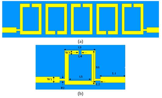
The
geometric of the proposed band-pass filter in this paper is shown in Figure 1 (a). The filter consists of 5 sets of open-loop
resonators and is powered through two 50Ω input impedance transmission
lines. The filter utilizes an FR4 substrate with dimensions h=1.55 mm, εr=4.4, and a loss tangent of 0.02. The
resonant frequency is chosen to be 4.2GHz, suitable for 5G applications. The
initial stage of the filter design involves creating a band-pass filter using
open-loop resonators. The design steps for the BPF, as described in the paper,
can be summarized as follows:
Step1.esigning a prototype of a
low-pass filter (LPF) with standardized characteristic impedance (g0)
and cutoff frequency (ωc).
Step2. Using certain
transformation techniques, the designed prototype of a low-pass filter can be
converted into a band-pass filter that operates at the desired resonant
frequency. This step will result in an integrated component circuit of
capacitors and inductors, forming a band-pass filter.
Step3. The Richard's
transformation is used to convert the band-pass filter into a microstrip planar
band-pass filter Hong and Lancaster (2004). The physical parameters
of the open-loop resonator filter without inner rings can be calculated using
the same design steps described in Hong and Lancaster (1997). The configuration and
optimized parameters of the BPF filter are shown in Figure 1(b) and Table 1, respectively.
Figure 1
|
Figure 1 (a) Five Order Open-Loop Resonator Band-Pass Filter Without Inner Rings (b) Open-Loop Resonator |
Table 1
|
Table 1 The Optimized Parameters of the Proposed Flat Filter (Units in Mm) |
||||||||
|
W1 |
W2 |
W3 |
L1 |
L2 |
L3 |
L4 |
L5 |
S1 |
|
1.19 |
0.4 |
0.8 |
4 |
0.8 |
5 |
0.43 |
3.7 |
6.98 |
Based on the literature, after calculating
the coupling coefficients, the next step is to determine the distance between
the resonators that matches the calculated coupling coefficients. To find this
distance, simulation results, particularly the S21 graph, need to be observed.
The spacing between coupled resonators affects the characteristics of the
filter. By varying the distance (L6) between the resonators and the number (N)
of hairpin resonators (N), the optimal design parameters for this study can be
determined. Figure 2 shows the simulation
results for five resonators with different L6 parameters (0.5~0.9mm). The
results indicate that as L6 increases, the center
frequency also increases, but the insertion loss increases as well, resulting
in poorer filter characteristics. At L6=0.5mm and N=5, the minimum insertion
loss is -3.21 dB at a resonant frequency of 4.21 GHz; however, the return loss
is (20 dB), and there is still room for further improvement.
Figure 2
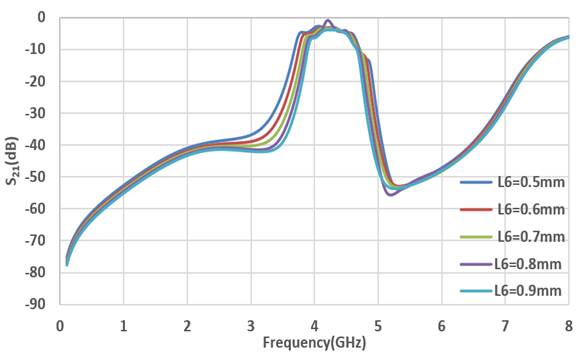
|
Figure 2 Simulation Results for Different L6 Parameters (N=5) |
Table 2
|
Table 2 The Simulated Data for the Characteristics of the Five-Order Filter with Different Coupling Distances (L6) |
|||
|
number
of hairpin resonators (N) |
coupling
distances L6 |
resonant
frequency (GHz) |
Insertion loss (dB) |
|
|
0.5
mm |
4.195 |
-3.21 |
|
N=5 |
0.9
mm |
4.265 |
-3.90 |
|
1.3
mm |
4.353 |
-5.31 |
|
2.2. Design of open-loop resonator filter with inner loop
The addition of an inner loop improves the
performance of the filter, especially in terms of frequency response and
selectivity. The inner loop introduces additional resonant modes into the
filter structure, which increases the degrees of freedom and allows for better
adaptation to specific frequency requirements. By adjusting the geometry and
dimensions of the inner loop, the resonant frequency, bandwidth, and
transmission characteristics of the filter can be modified. The inner loop also
provides additional coupling paths, which can alter the coupling effects and
transmission characteristics of the filter, further adjusting its performance.
Therefore, the addition of an inner loop enhances the performance and design
flexibility of the filter, making it more suitable for specific application
needs.
In this study, two types of inner loops were
attempted in the open-loop resonator: (1) an inner loop with a gap and an
opening in the same direction as the outer loop, and (2) a closed inner loop.
The geometry of the 5-order annular band-pass filter with an inner loop is
shown in Figure 3
Figure 3
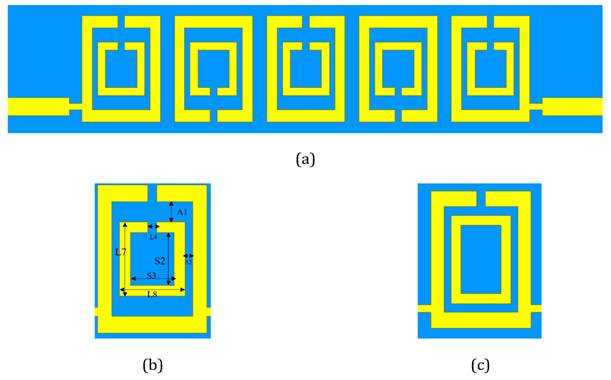
|
Figure 3 (a) 5 Order Band-Pass Filter with an Inner Loop (b) Inner Loop
with Gaps in the Same Direction as the Outer Ring (c)
Rectangular Inner Loop |
By modifying the line
width, shape, and the number of couplings in the filter, we can achieve the desired
frequency range and increase the bandwidth. The optimization parameters were
obtained through simulations using the HFSS software, as described in Table 3.
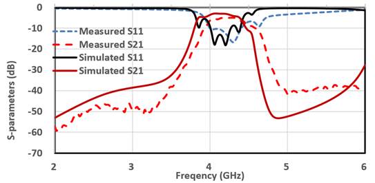
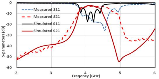
The S-parameter results from both simulation and measurement are shown in Figure 5 and Figure 6.
The simulation results of the
BPF with a co-directional gap loop show a -10dB bandwidth of 220MHz and an
insertion loss of -3.05 dB at 4.195GHz. The simulation results of the BPF with
a rectangular inner ring show a -10dB bandwidth of 180MHz and an insertion loss
of -3.21 dB at 4.195GHz. In addition, compared to a 5-order filter without the
added inner ring, the co-directional gap ring can improve the performance of
the filter in the passband.
Table 3
|
Table 3 The Optimized Parameters of the Proposed Flat Filter (Units in Mm) |
||||||
|
L7 |
L8 |
A1 |
A2 |
S2 |
S3 |
L4 |
|
5 |
3 |
0.7 |
0.4 |
4 |
2 |
0.43 |
Figure 4
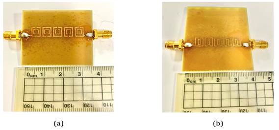
|
Figure 4 A Prototype of The Fabricated Filter: (a)
The Inner Loop with the Same Opening Direction as the Outer Loop,
(b) Rectangular Inner Loop
Without Gap |
Figure 5
|
Figure 5 Simulation and Measurement Results of A 4.2ghz Bandpass Filter with a Co-Directional Gap Loop |
Figure
6
|
Figure 6 Simulated and Measured Frequency Response of the Proposed 4.2ghz Bandpass Filter with a Rectangular Inner Loop |
3. Conclusion
This paper presents a systematic approach for designing bandpass filters by optimizing the filter characteristics through the addition of inner loops. The simulation results closely match the implemented results. In terms of implementation, the best results were achieved using a rectangular inner loop with five coupled resonators. The center frequency was 4.195 GHz, and the S21 value was -3.05 dB.
CONFLICT OF INTERESTS
None.
ACKNOWLEDGMENTS
None.
REFERENCES
Abdulraheem, Y. I., Abdullah, A. S., Mohammed, H. J., Mohammed, B. A., and Abd-Alhameed, R. A. (2014). Design of Radiation Pattern-Reconfigurable 60-GHz Antenna for 5G Applications. Journal of Telecommunications, 27(2), 7-11.
Al-Nuaimi, M. K. T., and Whittow, W. G. (2010). "Compact Microstrip Band Stop Filter Using SRR and CSSR Simulation and Results". In Proceedings of the Fourth European Conference on Antennas and Propagation, 1-5.
Al-Yasir, Y. I., OjaroudiParchin, N., Abdulkhaleq, A., Hameed, K., Al-Sadoon, M., and Abd-Alhameed, R. (2019). "Design, Simulation and Implementation of Very Compact Dual-band Microstrip Bandpass Filter for 4G and 5G Applications,". 16th International Conference on Synthesis, Modeling, Analysis. https://doi.org/10.1109/SMACD.2019.8795226.
Al-Yasir, Y. I., OjaroudiParchin, N., Alabdallah, A., Abdulkhaleq, A. M., Abd-Alhameed, R. A., and Noras, J. M. (2019). "Design of Bandpass Tunable Filter for Green Flexible RF for 5G". https://doi.org/10.1109/5GWF.2019.8911719.
Dahlman, E., Parkvall, S., and Skold, J. (2018). "5G NR : The Next Generation Wireless Access Technology. Academic Press.
Gil, M., Bonache, J., and Martin, F. (2008). "Ultra Compact Band Pass Filters Implemented Through Complementary Spiral Resonators (CSRs)," in IEEE MTT-S Int. Microw. Symp. Dig., Atlanta, GA, 1119-1122. https://doi.org/10.1109/MWSYM.2008.4633253.
Hong, J.-S. G., and Lancaster, M. J. (2004). Microstrip Filters for RF/Microwave, vol. 167. John Wiley and Sons.
Hong, J.-S., and Lancaster, M.J. (1997). 'Theory and Experiment of Novel Microstrip Slow-Wave Open-Loop Resonator Filter". IEEE Trans., MTT45, (12), 2358-2365. https://doi.org/10.1109/22.643844.
Hsu, C.-I G., Hsu, C.-C., Lee, C.-H., and Chen, S.-H. (2010). Balanced Dual-Band BPF Using Only Equal-Electric- Length Sirs for Common-Mode Suppression. Journal of Electromagnetic Waves and Applications, 24(5/6), 695-705. https://doi.org/10.1163/156939310791036241.
Hussaini, A. S., Abdulraheem, Y. I., Voudouris, K. N., Mohammed, B. A., Abd-Alhameed, R. A., Mohammed, H. J., Elfergani, I., Abdullah, A. S., Makris, D., Rodriguez, J., Noras, J. M., Nche, C., Fonkam, M. (2015). "Green Flexible RF for 5G," in Fundamentals of 5G Mobile Networks, J. Rodriguez, Ed : John Wiley and Sons, 241-272. https://doi.org/10.1002/9781118867464.ch11.
Mallahzadeh, A. R., Rahmati, B., Alamolhoda, M., Sharifzadeh, R. and Ghasemi, A. H. (2012). "Ultra Wide Stop Band LPF with Using Defected Microstrip Structures," in 2012 6th European Conference on Antennas and Propagation (EUCAP), 1-3. https://doi.org/10.1109/EuCAP.2012.6206280.
Nieto, J., and Sauleau, R. (2006). "Miniature Coplanar Waveguide and Microstrip Stop-Band Filters Using Spiral Resonators," in 2006 First European Conference on Antennas and Propagation, 1-5. https://doi.org/10.1109/EUCAP.2006.4585014.
Rodriguez, J., Radwan, A., Barbosa, C., Fitzek, F. H. P., Abd-Alhameed, R. A., Noras, J. M., Jones, S. M. R., Politis, I., Galiotos, P., Schulte, G., Rayit, A., Sousa, M., Alheiro, R., Gelabert, X., and Koudouridis, G.P. (2017). "SECRET-Secure Network Coding for Reduced Energy Next Generation Mobile Small Cells: A European Training Network in Wireless Communications and Networking for 5G." In 2017 Internet Technologies and Applications (ITA), 329-333. IEEE. https://doi.org/10.1109/ITECHA.2017.8101964.
 This work is licensed under a: Creative Commons Attribution 4.0 International License
© Granthaalayah 2014-2023. All Rights Reserved.