MILITARY BASED LANDMINE DETECTION ROBOTIC VEHICLE
Nandakumar K 1![]() , Kesavan R 2
, Kesavan R 2![]() , Niyasudeen N 2
, Niyasudeen N 2![]() , Surendra Prasad M 2
, Surendra Prasad M 2![]() , Vaseem Akram Y 2
, Vaseem Akram Y 2![]()
1 Assistant
Professor, Department of Electrical and Electronics Engineering, E.G.S. Pillay
Engineering College, Nagapattinam, Tamilnadu, India
2 UG
Scholar, Department of Electrical and Electronics Engineering, E.G.S. Pillay
Engineering College, Nagapattinam, Tamilnadu, India
|
|
|
ABSTRACT |
|
|
A landmine is
an explosive device which is concealed under the soil to destroy the enemy targets such as soldier, vehicle, tanks etc.
Landmines in India are mostly planted in fields, forest, wells, water
resources and energy production areas. The process of removing land mines
from a soil is called Demining or mine
clearance. In military operations, the deminig is
done with help of the devices such as mine plows and blast
waves. Sometimes specially trained animals also
involved in the process of mine clearance. These existing method requires a lot of time to remove the
landmine and which also involves loss of many lives during the demining
process. To avoid the hazard the landmine detection robot is proposed which
uses a ultrasonic sensor, metal detector and GSM
module as a complementary tool for landmine detection. The robot is used to
detects the position of the landmine and sends its GPS position to a web
server through GSM. |
|||
|
Received 10 April 2023 Accepted 11 May 2023 Published 31 May 2023 Corresponding Author Nandakumar
K, nandakumar071974@gmail.com DOI 10.29121/granthaalayah.v11.i5.2023.5146 Funding: This research
received no specific grant from any funding agency in the public, commercial,
or not-for-profit sectors. Copyright: © 2023 The
Author(s). This work is licensed under a Creative Commons
Attribution 4.0 International License. With the
license CC-BY, authors retain the copyright, allowing anyone to download,
reuse, re-print, modify, distribute, and/or copy their contribution. The work
must be properly attributed to its author.
|
|||
|
Keywords: GSM Module, Metal Detector, Landmine |
|||
1. INTRODUCTION
In war the buried
landmines plays a vital role. The untriggered
landmines are huge threats for civilans even after
end of the war. Landmines not only threat for soldiers as well as civilians
too. Landmines also causes huge problems to agricultural lands, water
reservoirs and development of roads in the regions of the borders. Basically,
the explosion of the landmine is caused by some triggering mechanisms. The
landmines are triggered by using the weight of the object. The landmines are
classified into many types depending upon the weight needed to trigger the
landmine. The landmines are require minimum pressure
of nine kilograms which is usually buried under the soil of 10 to 40 mm. Brown et al. (2002)
Landmines are used to
restrict the movements
of the enemy which are done by burying the landmines in certain patterns. One
of the pattern called Zigzag pattern which slows down
the movement of enemy. Landmines are also used to diverge the enemy from their
path and leads them in to middle of an ambush. Demining of the landmine from
the affected areas which require lots of human soldiers were used their lot of manpower,
time and efforts which shows in Figure 1. Animals also involves in the process of demining
like specially trained which helps verify and clear the affected area. This project aims to design a robot to detect the
landmines by using the GPS technology, metal detector and Arduino uno.
Figure
1

|
Figure 1 Landmine Detecting |
1.1. CLASSFICATION OF LANDMINES
Landmines are generally classified into two categories - Anti-Vehicle and Anti-Personnel. The anti-vehicle or anti-tank mines are require lots of pressure to activate and the footstep of a person is not enough for detonate them.
The required
pressure to detonate the anti-tank mines is between 348.33 pounds and 745.16
pounds i.e. (158 kilograms to 338 kilograms). Most of the tanks and other
military vehicles are very heavy and enough to produce the required amount of
pressure to detonate the mines. The Anti-personnel landmines are used
particularly to divert or drive back foot soldiers from the war zone. These
antipersonnel mines are generally get activated by pressure or by tripwire i.e.,
a wire stretched close to the ground or by remote detonation which is used to
kill their victims. Carullo (2001)
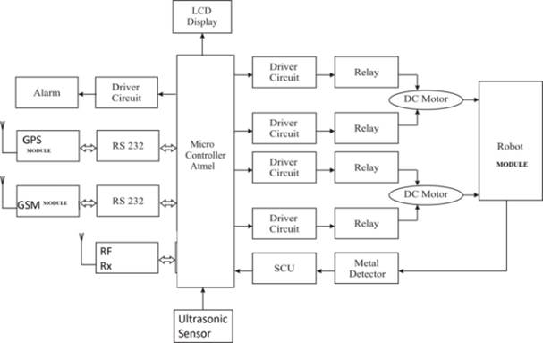
2. BLOCK DIAGRAM
The system
consists of several important components like Arduino, Metal detector,
Ultrasonic Sensor, Buzzer, LCD (Liquid Crystal Display), DC motor (Direct
Current Motor) are shown in Figure 2.
Figure 2
|
Figure 2 Block Diagram |
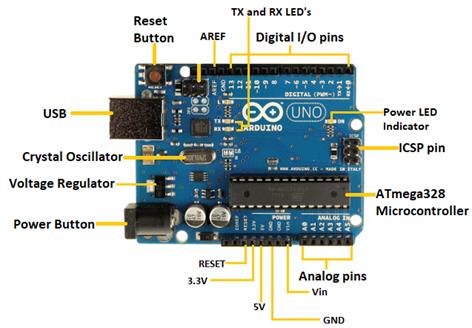
2.1. ARDUINO
Arduino Uno is the best board to get started with electronics and coding. It is commonly used in various projects and applications, including robotics, automation, home automation, and IoT (Internet of Things) projects. Arduino Uno is a familiar ATmega328P microcontroller is shown Figure 3.
It is commonly used in various projects and applications, including robotics, automation, home automation, and IoT (Internet of Things) projects. Arduino Integrated Development Environment (IDE), which is a software platform designed to program the Arduino uno. The Intgrated Development Environment allows users to frame the program, compile, and upload code to the board easily. Christ et al. (2011)
Figure 3
|
Figure 3 Arduino |
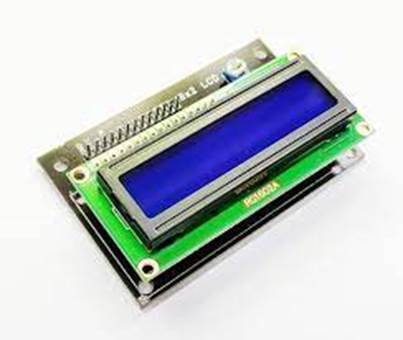
2.2. LCD (LIQUID CRYSTAL DISPLAY)
LCD display
(Liquid Crystal Display) is commonly used in electronic devices such as
calculators, watches, digital clocks, and many other electronic devices. It
consists of several layers of material that work together to display images and
text. Habib (2001)
The main component of an LCD display is a
layer of liquid crystals, which are placed between two polarizing filters. LCD
displays are commonly used in various applications such as medical devices,
automotive displays, home appliances, and more which is shown in Figure 3. They have become an essential component in
modern technology and continue to be developed with higher resolutions, faster
response times, and improved energy efficiency
Figure 4
|
Figure 4 LCD |
2.3. DC (DIRECT CURRENT) MOTOR
DC motor is device which is ued to converts electrical energy into mechanical energy. It works based on the principle of Fleming's left-hand rule and consists of a rotor and a stator. The rotor is the rotating part of the motor that contains the winding or permanent magnets, while the stator is the stationary part that contains the winding or magnets. Kuo-Lan et al. (2011)
The magnetic fields of the rotor and stator interact to produce a torque that rotates the shaft of the motor. They can also be classified based on their construction and speed, such as servo motor, compound motor and stepper motors. DC motors are popular due to their simplicity, reliability, and ease of control.
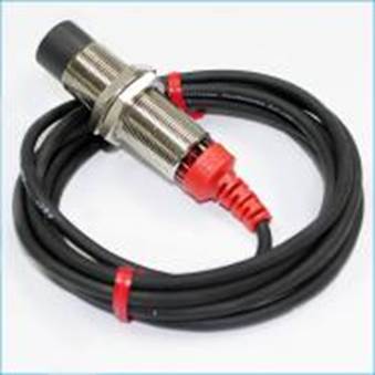
2.4. METAL DETECTOR
A metal detecting sensor is a type of sensor used to detect the presence of metal objects in a variety of applications. The sensor works by producing an electromagnetic field that interacts with the metal object and produces a change in the field, which is detected by the sensor. Metal detecting sensors are used in a wide range of applications, such as security systems, industrial metal detection, and consumer metal detectors. Metal detecting sensors are an important tool for detecting metal objects in a variety of applications, providing a non-invasive and effective way to detect metal objects, and ensuring the safety and security of people and valuable items.
Figure 5
|
Figure 5 Metal Detector |
2.5. ULTRASONIC SENSOR
An ultrasonic sensor which uses the ultrasonic sound waves to detect the presence of objects. It works by sending out high-frequency sound waves (typically above the range of human hearing) and measuring the time it takes for the waves to bounce back after hitting an object.
The sensor can
determine the distance to the object and whether it is moving or stationary by
using the reflecting waves and time taken by the wave to reflect
back from the target. Ultrasonic sensors is
used for many applications such as measuring the distance between objects,
obstacle detection, level sensing, and flow measurement. They are commonly used
in robotics, automation, and automotive industries, where accurate distance sensing
is critical for navigation and control
2.6. GPS MODULE
A GPS module is a device that receives signals from Global Positioning System (GPS) satellites and provides accurate location and time information to the user. The module contains a GPS receiver, which is responsible for detecting and decoding the signals from the GPS satellites, as well as a microcontroller that processes the data and provides the location and time information to other devices or applications. GPS modules are commonly used in a wide range of applications, including navigation systems for vehicles and boats, tracking systems for assets and people, and geotagging in photography. Some GPS modules also include additional features such as Bluetooth connectivity or an integrated antenna. GPS modules come in a variety of form factors, from small surface-mount components to larger standalone devices with integrated antennas. They can be interfaced with a wide range of microcontrollers and other devices using various communication protocols such as UART, SPI, or I2C.
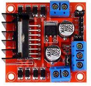
2.7. MOTOR DRIVER (L298N)
Motor driver is essential part to drive the motor accurately. Motor driver require supply voltage and current. It is used to operate the motors in both clockwise and anticlockwise direction. L298N is works on H-bridge principle. The motor driver works on 12v which is shown in Figure 6
Figure
6
|
Figure 6 Motor Drive |
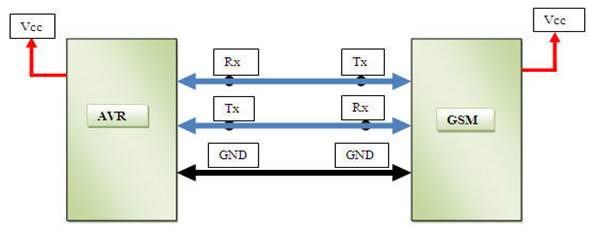
3. MICROCONTROLLER AND GSM MODULE CONNECTION
For microcontroller and GSM module connection, There are three pins in GSM modules are Transmitter pin (Tx), Receiver pin (Rx) and Ground pin (GND). The transmitter pin of GSM module is connected with receiver pin of the microcontroller and the receiver pin of GSM module is connected with the transmitter pin of microcontroller Also Ground Pin (GND) of GSM module is connected with the ground pin of microcontroller which shown in Figure 6.
Figure 7
|
Figure 7 Microcontroller and GSM Module Connection |
4. TOOLS IDENTIFIED
4.1. HARDWARE TOOLS
The hardware tools for prototype model of military based landmine detection
robotic vehicle and there components are listed below.
· Arduino Uno
· L298N (motor driver)
· Servo motors
· GPS module
· LM7805 IC
· Metal detector sensor
· DC motors
4.2. SOFTWARE
TOOLS
The Arduino IDE software is used for the model of military based landmine
detection robotic vehicle.
5. WORKING
The robotic vehicle consists of Arduino Uno connected with the wheels of
the robot for the movement of the vehicle in clockwise and anti-clockwise direction
over the land. In front side of robotic vehicle metal detector is placed which
can sense mine ahead of it. The robotic vehicles stop at that position when the robotic
vehicle found the landmine and send the co-ordinates to the mobile phone by
using the GPS module.
The latitude and longitude
information of a particular location of the landmine and transfer it to the blynk app at the controlling end. The ESP8266 is proficient
of either introducing an application or offloading all Wi-Fi networking functions
from other application. Which gets the latitude and longitude location through
online access and give it to the blynk app.
The robotic vehicle consist of two modules, which
are control station is used to control the robot from remote area. The control
station is consists of three integrated modules
consisting of Metal detecting component, GPS data collecting component and
Remote control component. These three components act as one system
but the original system components act as instantaneously working autonomous
systems.
6. RESULTS
· The Robot will be able to moves in all four directions: ie. Right, Left, Front, Back
· The Robot will be able to detect mine ahead of it.
· This model robot is cost effective because the structure is less complex. So it is easy to build a landmine detection robot.
· The robot gives exact co-ordinates of the landmine using GSM module.
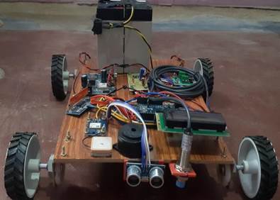
·
The final prototype of military based landmine detecting
robot vehicle is shown in Figure 7.
Figure 8
|
Figure 8 Prototype |
7. CONCLUSION
In the current examination of the existing prototype of automatic landmine detection robot has been presented and it can be made economically. The investment on landmine detection robot is made economical in the countries because this prototype is cost effective and less complex structure. The landmine detection robot is used to detect the landmines present under uneven ground surface. Once the robot detect the landmine which the produces buzzer sound to the user. And also send the coordinates of landmine which helps to diffuse the landmine safely, without the hazard of explosion.
CONFLICT OF INTERESTS
None.
ACKNOWLEDGMENTS
None.
REFERENCES
Brown, C., Zoubir, A.M., Chant, I.J, Abeynayake, C. (2002). Landmine Detection Using Single Sensor Metal Detectors. In Acoustics, Speech, and Signal Processing. https://doi.org/10.1109/ICASSP.2002.5745521.
Carullo, A., Parvis, M. (2001). An Ultrasonic Sensor for Distance Measurement in Automotive Applications. https://doi.org/10.1109/JSEN.2001.936931.
Christ, P., Neuwinger, B., Werner, F., Ruckert, U. (2011). Performance Analysis of the Nrf24l01 Ultra-Low-Power Transceiver in and Multi-Transmitter And Multi-Receiver Scenario. SENSORS, 2011 IEEE, Limerick, Ireland, 1205-1208. https://doi.org/10.1109/ICSENS.2011.6127100.
Habib, M. K. (2001). Mine Detection and Sensing Technologies-New Development Potentials in the Context of Humanitarian Demining. In Industrial Electronics Society. https://doi.org/10.1109/IECON.2001.975531.
Kuo-Lan, S., Hsu-Shan, S., Sheng-Wen, S., and JrHung, G. (2011). Motion Planning for a Landmine-Detection Robot. Artif Life Robotics 16, 277–280. https://doi.org/10.1007/s10015-011-0879-y.
 This work is licensed under a: Creative Commons Attribution 4.0 International License
© Granthaalayah 2014-2023. All Rights Reserved.