COMPARISON OF FORGING LOAD, MATERIAL FLOW AND PRESSURE DISTRIBUTION OF THE UNI-DIRECTIONAL, BI- DIRECTIONAL AND TWO-STEP FORGING PROCESSES
Omer Eyercioglu 1![]() , Gulaga Tas 2
, Gulaga Tas 2![]()
1 Department
of Mechanical Engineering, Gaziantep University, Gaziantep, Turkey
2 Aeronautics
and Aerospace Engineering Department, Hasan Kalyoncu
University, Gaziantep, Turkey
|
|
|
ABSTRACT |
|
|
Because of
high productivity, closer dimensional tolerances, and minimal material waste
precision forging (net or near net shape) processes have been used for
manufacturing automobile components. The primary disadvantage of precision
forging is the encountered higher tool stresses due to applied higher forging
loads. Thus, forging load reduction is a higher priority in precision forging
in terms of energy consumption and cost because higher loads required higher
investment and higher energy consumption. Forging load is affected by several
parameters such as temperature, material flow, the geometry of the billet,
and punch movement. In this study, forging load, material flow, and normal
pressure distribution in the forged part were investigated considering uni-directional, bi-directional, and two-step forging
processes. FEM simulations were performed by using a solid cylindrical
billet. To perform FEM simulations, the finite element analysis package
(DEFORM 2D) was used. Also, experimental studies of the FEM models were
performed. For bi-directional and step-forging experimental studies, a
double-acting servo press was used because the movement of the top and bottom
punch can be controlled accurately. Then the results of FEM and experimental
studies were compared with each other. The results of the FEM simulations and
experimental studies show two-step forging offers lower forging load and
energy consumption whereas the uni-directional
closed die forging process needs higher load and energy consumption. |
|||
|
Received 26 November 2022 Accepted 28 December 2022 Published 13 January 2023 Corresponding Author Omer Eyercioglu, eyercioglu@gantep.edu.tr
DOI10.29121/granthaalayah.v10.i12.2022.4970 Funding: This research
received no specific grant from any funding agency in the public, commercial,
or not-for-profit sectors. Copyright: © 2022 The
Author(s). This work is licensed under a Creative Commons
Attribution 4.0 International License. With the
license CC-BY, authors retain the copyright, allowing anyone to download,
reuse, re-print, modify, distribute, and/or copy their contribution. The work
must be properly attributed to its author.
|
|||
|
Keywords: Forging Load, Bi-Directional Forging,
Uni-Directional Forging, Closed Die Forging |
|||
1. INTRODUCTION
In order to form a complicated shape forging that has no flashes, enclosed die forging that uses one or more punches to squeeze the workpiece in a pre-enclosed die has been developed since the 1970s Kopp (1996), Nakano (2010) . When cross-checked with the open die forging, the workpiece is compressed between the punch and die set, and the cavity of the die can be filled under a lower forming load due to the reduction of the contact area between the loading punch and the billet. However, as the workpiece material flows and especially fills the die cavity, the forming load raises drastically. Therefore, it is very important to decrease the forming load at the final stage of the process Shinozaki (1992), Ohga and Kondo (1993). Moreover, the material flow in fully enclosed die forging is more complex and difficult to forecast. The forging defects such as laps, folds, non-filling of dies, etc. may form. This result in the production of forged parts with defects that are not desirable for final finishing processes. The finite element analysis (FEA) software has allowed this whole forging process to be simulated and it has allowed the prediction of all the necessary stress–strain states in both the workpiece and the die set Maccormack and Monaghan (2002).There are many studies that analyzed the forging process by using finite element simulations in terms of forging load, and material flow, and analyzing the gear forging process Zhuang et al. (2019), Al-Shammari et al. (2018), Rajesh et al. (2022), Ji et al. (2022), Paramasivam et al. (2019), Obiko et al. (2019), Osakada et al. (2011). Recently, there has been a widening demand for developing a forging process that uses the servo-press for the forging industry all around the world. The development of servo-presses allows for realizing the complex and flexible press motion during the manufacturing processes Osakada (2010), Nakano, (2010), Kawamoto and Klumb (2012), Osakada et al. (2011). The servo die cushion is used as a back pressure load generator to determine its effect on the accuracy of the shape of the formed part and total forming load in cold forging. It has been shown that the back pressure enabled better die filling with a lower load Kawamoto et al. (2014). The forging load can be reduced, and the metal flow can be improved by using bi- directional loading for H-shape axisymmetric part Yetkin et al. (2016).
In this study, uni-directional, bi-directional and two step forging process were utilized to examine the metal flow and forging load. These types of forgings were compared with respect to forging load and material flow. Forged part of Lead was modelled and simulated by using the finite element analysis package (DEFORM 2D) and the results are presented. Also, experimental studies were performed. The results of the experimental studies and FEM simulations were compared with respect to forging load and material flow.
2. FINITE ELEMENT MODELLING AND EXPERIMENTAL STUDIES
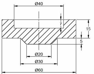
In order to obtain final geometry shown in Figure 1 -after forging processes- three types forging processes were performed. These are uni-directional, bi-directional and two step forgings.
Figure 1
|
Figure 1 Final Shape |
2.1. Finite Element Modelling
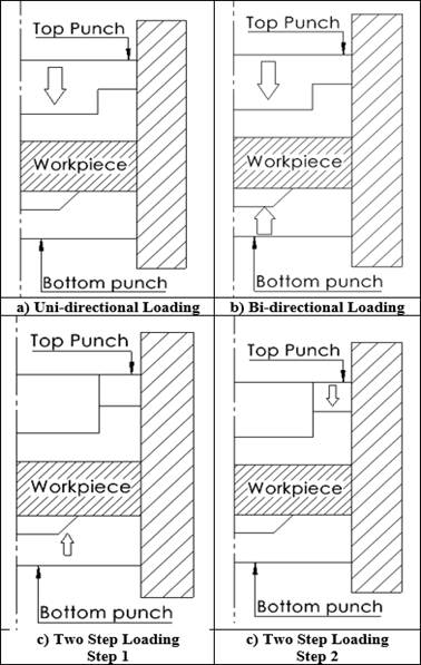
Because DEFORM was especially designed for forming processes, it was used for the finite element modelling of the forging processes. Due to work piece geometry, two-dimensional modelling was used. In the FEM modelling, in order to perform simulations in a possible shorter time, half of the specimen geometry was used. The dimensions of the work piece were determined by using volume constancy. Work pieces were considered as elastoplastic and work piece material was selected from the DEFORM database as Lead. By using automatic mesh generation, work piece was divided into elements. The dies were considered as rigid material so no need to assign a material type for the dies. In the bi- directional forging upper punch speed was selected as 1mm/s and bottom punch was considered as stationary. In the bi-directional forging upper and bottom punch speed were determined as 1mm/s. In the two steps forging firstly the bottom punch were moved then it was stopped, after that the upper punch were moved and the speed for both were selected as 1 mm/s. Friction coefficient between the dies and work piece were assumed to be 0.3. During the forging process were selected as 20oC. In the finite element simulations, the Lagrangian incremental solver and the Newton-Raphson iteration method were used. The AMG (Automatic Mesh Generator) that automatically provides an optimized re-meshing capability is used to solve large deformation problems in DEFORM. Finite element models of forging processes can be seen in Figure 2.
2.2. Experimental Studies
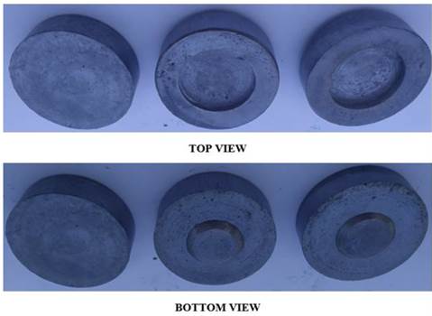
For the experimental studies, a servo press that has two moveable punches driven by the servo motors were designed. In order to plot load-stroke diagram, load cells and linear encoders are attached to the servo-press. The die was placed and fixed on the press bed. Die set is mainly consist of three parts: container, top punch, and bottom punch. The forging process was performed step by step to examine the shape of the forged part in the intermediate steps. Final and intermediate shape of the forged part can be seen in Figure 3.
3. RESULTS AND DISCUSSIONS
3.1. Material Flow
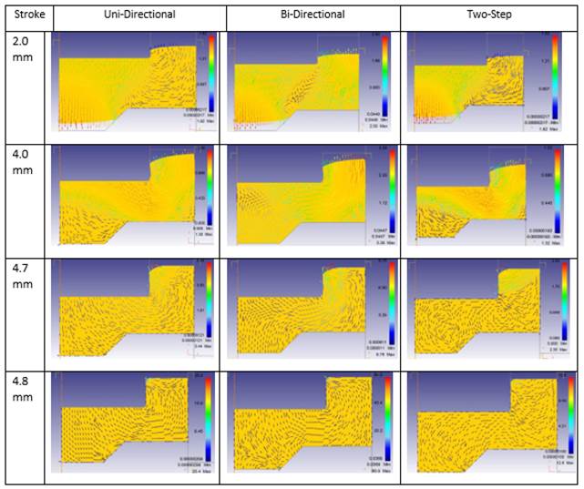
Material flow of the three different forging processes can be seen in Figure 4. In the uni- directional forging process material flows outward and downward. Once the bottom cavity is filled, material flows outward and fills the outer corner of the die. Then the material squeezed and subjected to flow into inner cavity of the die by both punches. In the beginning of the bi- directional forging firstly a vortex occurs in the shear zone which is the region between the bottom and upper die cavities. Then the material flows downward and upward and firstly fills the bottom cavity. After that all material are subjected to flow by both punches and finally material fills the inner corner of the die. In the two-step forging process, firstly, bottom punch is moving and causes to material flow upward and relatively downward. After a certain stroke, bottom die stops, and material fills the bottom cavity of the die. Then the top punch moves and causes to material flow. In this step only a part of material is subjected to move and finally the material fills the outer and inner corner of the die
Figure 2
|
Figure 2 Finite Element Models of Forging Processes: A) Uni-Directional, B) Bi-Directional And C) Two-Step |
Figure 3
|
Figure 3 Final and Intermediate Shape of The Forged Part |
3.2. Forging Loads
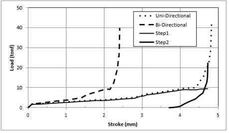
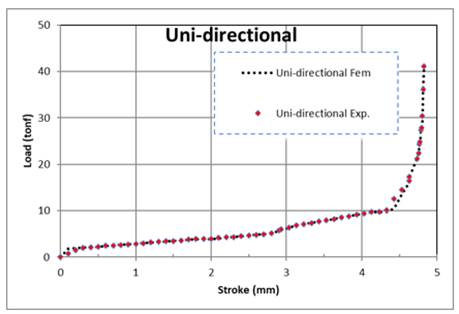
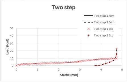
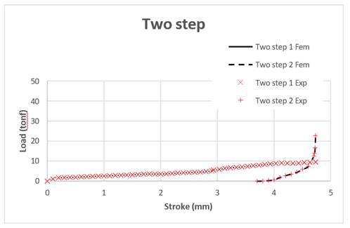
Comparison of the load stroke diagrams for three different forging processes is given in Figure 5. Also, comparison of, FEM and experimental load stroke diagrams of each forging process are given through Figure 6, Figure 7, Figure 8. As can be seen in figure, load stroke diagram of bi-directional and uni-directional forging processes show nearly same characteristics while the stroke of the bi- directional forging is half of the stroke of the uni-directional forging. Maximum forging load for uni-directional and bi-directional forging process are very close to each other and maximum forging load for uni-directional forging is 42 tonf and for bi-directional forging is 39.7 tonf. Maximum forging load for two step forging is drastically lower than the uni-directional and bi- directional forging because of that in the first step material flows freely and in the second step friction surface between the dies and workpiece is reduced hence friction force reduced and this causes a reduction on the forging load. Forging load for first step and for second step is 10.1 and 22.5 tonf respectively.
Figure 4
|
Figure 4 Material Flow Pattern of the Forging Processes |
Figure 5
|
Figure 5 Load Stroke Diagrams of Forging Processes (Fem) |
Figure 6
|
Figure 6 Comparison of Load Stroke Diagram of Uni-Directional Forging Process |
Figure 7
|
Figure 7 Comparison of Load Stroke Diagram of Bi-Directional Forging Process |
Figure 8
|
Figure 8 Comparison of Load Stroke Diagram of Two Step Forging Process |
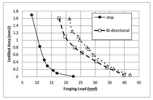
When the punches moved, the work piece flows and fills die cavities and forging load gradually increases. At the last period of the forging process forging load asymptotically increases and unfilled area of die cavity decreases. The unfilled area and corresponding forging load were determined from the FEM simulations and can be seen in Figure 9
Figure 9
|
Figure 9 Relation of The Unfilled Area and the Forging Load |
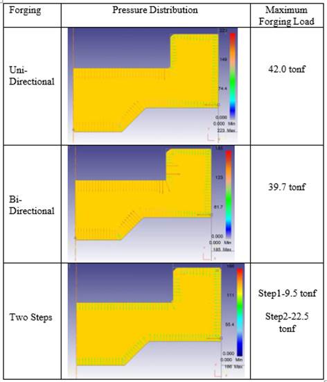
During the forging processes die components subjected to higher internal pressure and this decrease the fatigue life of the die components and increase the cost of the product. Therefore, for the loading conditions (uni-directional, bi-directional and two step forgings), normal internal pressure distribution of the die components determined from the simulations. As can be seen in Figure 10 the two steps forging considerably reduces the internal pressure on the die components.
4. CONCLUSIONS
· From the FEM and experimental studies, the followings can be concluded.
· Experimental studies and FEM simulations are in well agreement
· Forging load considerably can be reduced by using two step forging process
· Unfilled area in two step forging is less than that of the bi-directional and uni-directional forgings.
· Internal pressure acted on the die components is reduced by using two step forging, therefore the fatigue life of die components is increased, and cost of the forging part is reduced.
· During the last step of forging processes, in the uni-directional and bi-directional forging processes all material is subjected to flow and to complete die filling. On the other hand, in the two-step forging process only a little portion of material is subjected to flow and to complete die filling. This is in turn considerably reduced the forging load.
Figure 10
|
Figure 10 Normal Pressure Distribution of Loading Conditions |
CONFLICT OF INTERESTS
None.
ACKNOWLEDGMENTS
None.
REFERENCES
Al-Shammari, M. A., Zedan, L. Y., and Al-Shammari, A. M. (2018). ‘FE Simulation of Multi-Stage Cold Forging Process For Metal Shell of Spark Plug Manufacturing,’ 1st International Scientific Conference f Engineering Sciences - 3rd Scientific Conference of Engineering Science (ISCES), 2018, 209-214. https://doi.org/10.1109/ISCES.2018.8340555.
Ji, H., Song, G., Huang, X., Li, J., Pei, W., and Xiao, W. (2022). Precision Hot Forging Forming Experiment And Numerical Simulation of A Railway Wagon Bogie Adapter. International Journal of Advanced Manufacturing Technology, 120(1–2), 907–925. https://doi.org/10.1007/s00170-022-08810-3.
Kawamoto, K., Yoneyama, T., Okada, M., Kitayama, S., and Chikahisa, J. (2014). Optimum Back-Pressure Forging Using Servo Die Cushion. Procedia Engineering, 81, 346–351. https://doi.org/10.1016/j.proeng.2014.10.004
Kawamoto, K., and Klumb, D. (2012). Future application of AC servo press focusing on forging process. In Proceedings of the 45th ICFG Plenary Meeting, 113–116.
Kopp, R. (1996). Some Current Development Trends In Metal Forming Technology. Journal of Materials Processing Technology, 60(1–4), 1–9. https://doi.org/10.1016/0924-0136(96)02301-1
Maccormack, C., and Monaghan,
J. (2002). 2D and 3-D Finite Element Analysis of a
Three-Stage Forging Sequence. Journal of Materials Processing Technology,
127(1), 48–56. https://doi.org/10.1016/S0924-0136(02)00254-6.
Nakano, T. (1994). Modern Applications
of Complex Forming and Multiaction Forming in Cold Forging. Journal of
Materials Processing Technology, 0136(94)90111-2), 201–226. https://doi.org/10.1016/0924-0136(94)90111-2.
Nakano, T. (2010). Press Machine Trends And Servo Press Forming Examples. Steel Research International.
Obiko, J. O., Mwema, F. M., and Bodunrin, M. O. (2019).
Finite Element Simulation of X20crmov121 Steel Billet Forging Process Using The
Deform 3D Software. SN Applied Sciences, 1(9), 1–10. https://doi.org/10.1007/s42452-019-1087-y.
Ohga, K., and Kondo, K. (1993). Research on Application Range of The Precision Cold Die Forging Utilizing Divided Flow To Thick Products. Proceedings Of The 4th ICTP.
Osakada, K. (2010). Application of Servo Presses To Metal Forming Processes. Steel Research International, 9–16.
Osakada, K., Mori, K., Altan, T., and Groche, P. (2011). Mechanical Servo Press Technology for Metal Forming. CIRP Annals, 60(2), 651–672. https://doi.org/10.1016/j.cirp.2011.05.007.
Paramasivam, S. S. S. S., Kumaran, D., Natarajan, H., and Mishra, A. (2019). Numerical Simulation of Cold Orbital Forging Process For Gear Manufacturing. International Journal of Modern Manufacturing Technologies, 11(2), 126–132.
Rajesh, K. V. D., Buddi, T., and Mishra, H. (2022). Finite Element
Simulation of Ti-6Al− 4V Billet on Open Die Forging Process Under
Different Temperatures Using DEFORM-3D. Advances In Materials and Processing
Technologies, 8(2), 1963–1972. https://doi.org/10.1080/2374068X.2021.1878708.
Shinozaki, K. (1992). Manufacturing of Precision Products By Enclosed Die Forging. Journal Of Materials Processing Technology, 784–793.
Yetkin, O., Eyercioglu, O., and Tandogan, M. (2016). International Mechanical Engineering and Technologies Conference. Forging Load Evaluation of Axially Symmetrical Parts of Bi-Directional Forging Process, Mechatech, 29–30, 48–56.
Yoshimura, H. and Tanaka, K. (2000). Precision Forging of
Aluminum and Steel, Journal of Materials Processing Technology. https://doi.org/10.1016/S0924-0136(99)00199-5.
Zhuang, W., Han, X., Hua, L., Xu, M., and Chen, M. (2019). FE Prediction Method For Tooth Variation in Hot Forging of Spur Bevel Gears. Journal of Manufacturing Processes, 38, 244–255. https://doi.org/10.1016/j.jmapro.2019.01.022.
 This work is licensed under a: Creative Commons Attribution 4.0 International License
© Granthaalayah 2014-2022. All Rights Reserved.