ANALYSIS OF PID CONTROLLER USE ON AUXILIARY WINDING INDUCTION MOTOR WITH FUZZY LOGIC METHODHartono 1 1 Electrical Engineering Departement, Universitas Sultan Ageng Tirtayasa, Cilegon, Indonesian. |
|
||
|
|
|||
|
Received 3 August2021 Accepted 19 August2021 Published 31 August 2021 Corresponding Author Hartono,
sallam.hartono@yahoo.com DOI 10.29121/granthaalayah.v9.i8.2021.4205 Funding:
This
research received no specific grant from any funding agency in the public,
commercial, or not-for-profit sectors. Copyright:
© 2021
The Author(s). This is an open access article distributed under the terms of
the Creative Commons Attribution License, which permits unrestricted use, distribution,
and reproduction in any medium, provided the original author and source are
credited.
|
ABSTRACT |
|
|
|
Controlling
the control of an induction motor with a stable and fast speed is very much
needed in the industrial. To get a constant speed and be able to improve the
performance of the induction motor, a PID controller circuit is needed. Fuzzy
logic method is known to work with a fast response and enough good
performance. The value of the motor speed formed with PID control and fuzzy
logic, the rotor speed with fuzzy is the same as that without using fuzzy of
1785 rpm with the same overshoot and fuzzy rise time value of 346,605 ms and
the value of rise time without fuzzy of 346,111 ms. The results obtained in
the Main current without fuzzy of 2.2 A, main current with fuzzy of 2.2 A,
aux. Current without fuzzy is 1.6 A, aux. Current with fuzzy 1.9 A,
load and elctromag torque without fuzzy no value, load and elctromag torque
with fuzzy no value, main voltage without fuzzy 154 V, main voltage with
fuzzy 154 V, aux. Voltage without fuzzy 180 V, aux. Voltage with fuzzy is 184
V, rotor speed without fuzzy is 1785 rpm, rotor speed with fuzzy is 1785 rpm. |
|
||
|
Keywords: Induction
Motor, PID, Fuzzy Logic 1. INTRODUCTION Induction motor is one
type of electric motor that works based on electromagnetic induction. Single
phase induction motors are very often used in daily needs in jobs that
require low power and relatively constant speed. The induction motor has a
source of electrical energy on the stator side, while the electrical system
on the rotor side is induced through the air gap of the stator by means of an
electromagnet. This is called an induction motor. The use of induction motors
in this industry is as a driver, such as for blowers, compressors, pumps,
prime movers of production processes or mills, workshop equipment such as
drilling machines, grinders, cranes, and so on F. Arvianto and M.
Rameli (2017). The advantages of
induction motors are simple and sturdy construction, relatively cheap price
and easy maintenance. However, the weakness of the induction motor is that it
is unable to maintain a constant speed when there is a change in speed or a
change in load torque. To get a constant speed and be able to improve the
performance of an induction motor, a controller circuit is needed. The
control circuit that is commonly used is the PID controller
(Proportional-Integral-Derivative) R. Gunawan et al. (2010). PID control is a
combination of proportional control, integral control, and derivative
control. The proportional controller is a control that serves to amplify |
|
||
the driving error signal (error signal), so that it will accelerate the system output to reach the reference point. The integral control is the change from the integral control output m(t), changing with a function of time which is proportional to the error signal. Derivative control is often called rate control, because the controller output is proportional to the rate of change of the error signal. This combination of controls has the advantage of correcting signal errors compared to each of the three controls A. Faizal and V. D. Sinta (2018).
The Proportional Integral Derivative (PID) controller is the most widely used controller in the control system field in the industrial world. The three constants on the PID in parallel can cover any shortcomings and advantages of each constant so that a good controller is obtained N. Evalina and A. A. Zulfikar (2018). In this study, the installation of a PID (Proportional-Integral-Derivative) controller will be simulated on an induction motor. The weakness of using a conventional PID controller in setting the speed of an induction motor is the difficulty in determining the appropriate parameter value (gain) D. Sasmita et al. (2016). The solution, in this research, researchers develop a control system based on fuzzy logic technology. Logic controllers fuzzy known to work with fast response and good enough performance. From the simulation made using Simulink, the result is that the fuzzy logic controller system can improve the performance of induction motor speed regulation by minimizing spikes and recovery time to reach the setpoint, so the theme is "Analysis of the use of PID Controller on auxiliary winding induction motors with fuzzy logic method “.
2. LITERATURE REVIEW
2.1. INDUCTION MOTOR
Motor induction is is the motor electric alternating (ac), which rounds the rotor is not equal to the rotation field of the stator, in other words, rotation of the rotor with the rotation field of the stator there is a difference in rotation which is called slip. In general, the motor induction is known there are two kinds based on the number of phases are used, namely: motor induction one phase and the motor induction three- phase C. Ning (2016). In accordance with its name motors induction of the phase is designed to operate using a supply voltage of one phase. However, this motor also has some drawbacks, namely a relatively low loading capacity, unable to initiate self- starting without the aid of assistive devices and low efficiency L. Wang et al. (2015).
2.2. PID Controller
In this research proportional – integral – derivative controller is used because it is a feedback loop control mechanism which is widely used in industry. One of the tasks of the PID controller is to reduce the error signal, namely the difference between the setting signal and the actual signal. The faster the response of the controller and the smaller the error value obtained, the better the PID controller will be F. Yusivar and N. Avianto Wicaksono (2016).
2.3. LOGIC CONTROLLERS FUZZY
Controller logic fuzzy categorized under the control of intelligent (intelligent control). Logic unit fuzzy has the ability to resolve the problem behavior system that complex, which is not owned by the controller of conventional F. M. W. Fatih Mutamimul Wildan (2016).
1) Fuzzification
In the process of fuzzification, occur conversion variables crisp to the variable fuzzy through techniques membership function [10], with error and delta error is mapped into the range of the working universe of discourse through the equation below:
𝑄𝑒(𝑘) = 𝐺1𝑥 𝑒(𝑘) (1)
D 𝑄𝑒(𝑘) = 𝐺2𝑥 D𝑒(𝑘) (2)
2) Membership Function
Membership Function (membership function) fuzzy set is a function to express membership of the value. Some forms of membership functions are triangular (triangular), trapezoidal (Trapezoidal).
3) Fuzzy Implication
In general, fuzzy rules are expressed in the form of IF - THEN logic which is the basis of fuzzy relations E. Wahjono (2015). Relation fuzzy (R) in the base of knowledge of fuzzy is defined as a function of the implications of fuzzy (fuzzy implication). Some fuzzy implication functions are shown in Table 1.
|
Table 1 Several types of fuzzy implication functions |
|
|
Name |
Implication
Operators ɸ [μ𝐴 (𝑥), μ𝐵 (𝑦)] = |
|
Zadeh Max-Min |
(μ𝐴(𝑥) 𝖠 μ𝐵(𝑦)) ⋁ (1 − μ𝐴(𝑥)) |
|
Mamdani Min |
μ𝐴(𝑥) 𝖠 μ𝐵(𝑦) |
|
Larsen Product |
μ𝐴(𝑥). μ𝐵(𝑦) |
|
Arithmetic |
1 𝖠 (1 − μ𝐴(𝑥) + μ𝐵(𝑦)) |
|
Boolean |
(1 − μ𝐴(𝑥)⋁μ𝐵(𝑦)) |
4) Defuzzification
Defuzzification is the opposite of the process of transforming a fuzzy set into a set of tasks D. R. Irawan (2016). The most commonly used defuzzification method is Center of Gravity (COG) defuzzification. The simulation results that have been achieved show that the fuzzy logic controller is able to suppress the decrease in motor performance against changes in load and speed below 1% when compared to the use of a conventional controller (PID). The control system developed is able to meet the criteria of the performance of the system are high.
3. RESEARCH METHODOLOGY
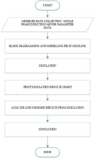
In the section of this will be explained the methodology of the study were used, in the form of design which includes diagrams flow research, diagram block research and schematic circuit devices in the simulation. Figure 1. is a research flowchart
|
|
|
Figure 1 Research Flowchart |
|
|
|
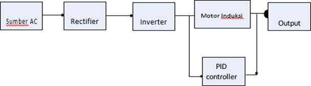
Figure 2 Research Block Diagram |
This design focuses on the performance of the induction motor system. The system consists of a filtered and signal- converted power source and is controlled by a PID control system. The design is shown in Figure 2.
Motor Speed Control Block Diagram With PID
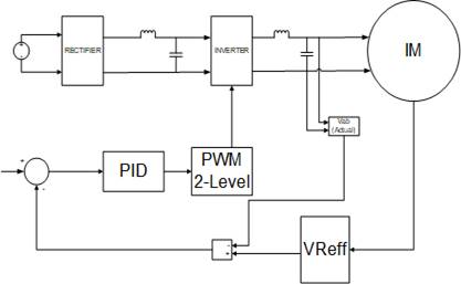
A block diagram of motor speed control with PID is required to control the speed of the motor. It should also be noted that each element of all installed components can work according to the commands that have been given. Figure 3. shows a block diagram of motor speed control with PID.
|
|
|
Figure 3 Block Diagram of Single-Phase
Main and Auxiliary Winding Motor Speed Control With PID |
Figure 3 illustrates the speed control setting of the axial winding induction motor. The incoming power source will be filtered by the rectifier so that it becomes a smooth signal wave. Then it will be converted back into an alternating wave (AC). After that if the input voltage must match the reference voltage. After the reference voltage is appropriate, the PID will control and PWM will bring a better signal to the inverter so as to produce a stable speed.
Motor Speed Control Block Diagram with PID And Fuzzy
Logic
|
|
|
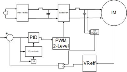
Figure 4 Block Diagram of Single-Phase
Main and Auxiliary Winding Motor Speed Control with PID Control with Fuzzy
Logic |
The block diagram for controlling motor speed with PID is needed to control the speed of the motor and maximize it using the fuzzy logic method. It should also be noted that each element of all installed components can work according to the commands that have been given. Figure 4. shows a block diagram of motor speed control with PID and Fuzzy Logic.
Speed Controller Block in Simulink Matlab
|
|
|||
|
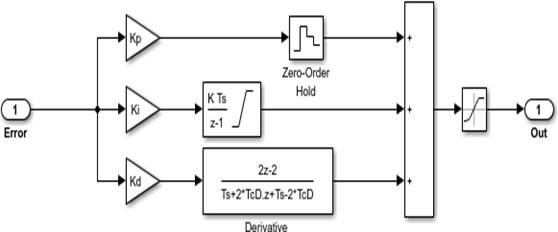
Figure 5 PID Controller |
Figure 5. That is by using the PID Controller where the error at the input is based on the reference voltage to control the motor rotation as desired. And the saturation block is an output signal generator which is limited by the upper and lower limit parameters.
Fuzzy Control –PID
In addition to using PID control, but also using FUZZY LOGIC CONTROL-PID. Here is a picture of control Fuzzy Logic Control- PID are contained in the block speed Controller:
|
|
|
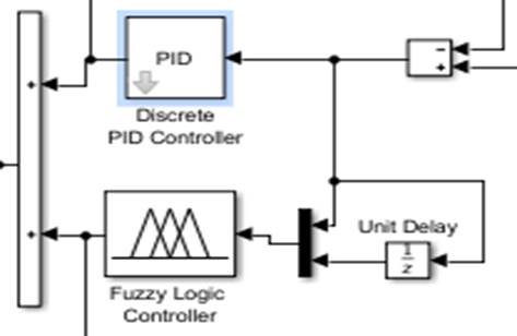
Figure 6 Fuzzy-PID Controller |
Figure 6. is a fuzzy-pid controller that can change the shape of the signal according to the desired reference that is set. In this fuzzy-pid controller system, the error rate and deltaerror changes are obtained as input and output1 as a request to improve the speed rate so that the signal can be better. The MAMDANI method and the defuzzification method can be seen in the table below as the definition of control.
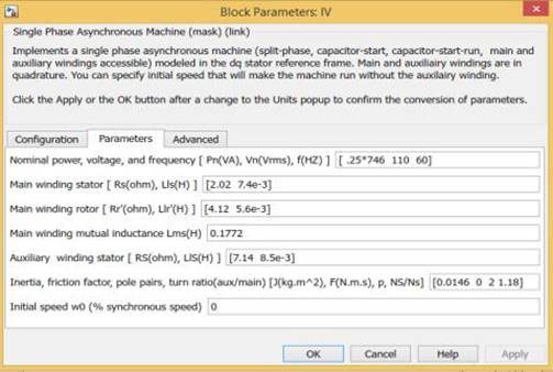
Motor Block Main and auxiliary winding
The following main and auxiliary winding motor blocks are asynchronous machines. Type of motor play and the auxiliary winding are used that type of squirrel - cage. The input is in the form of load torque. The following is the main and auxiliary winding motor block in Figure 7, the main and auxiliary winding motor configuration block in Figure 8, and the main and auxiliary winding motor parameter block in Figure 9.
|
|
|||
|
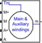
Figure 7 Motor Block Main and auxiliary winding
on Simulink Matlab |
|
|
|
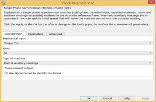
Figure 8 Motor Configuration Block Main
and auxiliary winding in Simulink Matlab |
|
|
|
Figure 9 Motor Parameter Block Main and
auxiliary winding on Simulink Matlab |
4. RESULTS AND DISCUSSIONS
This section describes the results of testing by comparing the results of the simulation control the speed of the motor to play and the auxiliary winding one phase to the control of the PID, and control of the FUZZY LOGIC. Where the performance of the work of the PID and FUZZY LOGIC as controlling the speed of rotating the motor to play and the auxiliary winding to be tested. This is necessary to know the response of the system that is working. After each section gets the test results, an overall test will be carried out to determine its condition and performance.
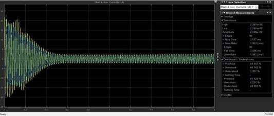
Main Current and Aux.Current Simulation Results
Without Fuzzy
The results of the Main Current simulation on the single-phase main and auxiliary winding motor can be seen in Figure 10.
|
|
|
Figure 10 Graph of Main Current
Simulation Results without fuzzy |
The results obtained on the main current in the time range 0 s - 0.2 s with a yellow wave from 23.47 A decreased to 15 A. If in a span of 0:21 s-0.4 s in the main current of 14 A decreased to 5 A. In a span of 0.6 s- 2s on the main current is stable at a current of 2.2 A. The results were obtained in which the main current to overshoot 46 742 % and rise time 3. 517 ms.
|
|
|
Figure 11 Graph
of Aux Simulation Results. Current without fuzzy |
Results obtained on Aux. Current in the time range 0 s- 0.2 s with a blue wave from 21 A-12 A. If in the time range 0.21 s-0.4 s the aux current is 12 A-4 A. In the time range 0.6 s-2s on aux. current in the range of 0.6s - 2s is stable with a current of 1.6 A. Results on aux. current with overshoot 123.140% and rise time 1.342 ms.
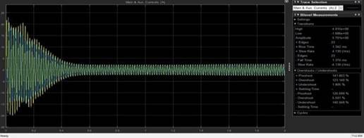
Main Current and Aux. Current Simulation Results with
Fuzzy
|
|
|
Figure 12 Graph
of Main Current Simulation Results with fuzzy |
The results obtained on the main current in the time range 0 s - 0.2 s with a yellow wave from 23.37 A decreased to 15 A,. If in a time span of 0.21 s-0.4 s the main current of 14 A decreases to 5 A. In a time, span of 0.6 s-2s the main current is stable at a current of 2.2 A. The results obtained where the main current with overshoot 38.468% and rise time 3,793 ms.
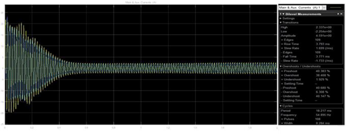
|
|
|
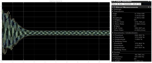
Figure 13 Graph
of Aux. Current Simulation Results with fuzzy |
Results obtained on Aux. Current in the time range 0 s- 0.2 s with a blue wave from 22 A-12 A. If in the time range 0.21 s-0.4 s on aux. current of 12 A - 4 A. In the span of 0.6 s - 2s on aux. current in the range of 0.6s - 2s is stable with a current of 1.9 A. Results on aux. current with an overshoot of 173.436% and a rise time of 574,748 micro seconds.
Rotor Speed Simulation Results Without Fuzzy
|
|
|
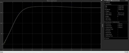
Figure 14 Graph
of Rotor Speed Simulation Results without fuzzy |
The results obtained in the obtained results where the rotor speed at a time of 0.5 s with a speed of 1791 rpm and at a time of 1.5 s with a speed of 1785 rpm, where the overshoot on the rotor speed graph with a result of 0.505 % and a rise time with a result of 346,111 ms.
Simulation Results of Rotor Speed with Fuzzy
|
|
|
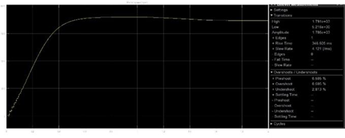
Figure 15 Results
of Rotor Speed with Fuzzy |
The results obtained in the obtained results where the rotor speed at a time of 0.5 s with a speed of 1791 rpm and at a time of 1.5 s with a speed of 1785 rpm, where the overshoot on the rotor speed graph is 0.505 % and the rise time is 346.605 ms.
Simulation Results of Main Voltages
|
|
|
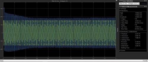
Figure 16 Graph
of Main Voltages Results Without Fuzzy |
The results obtained on the main voltages in the time range of 0 s- 0.4 s with a blue wave from 308 V decreased to 200 V. In the time range of 0.6 s-2s the main voltages were stable with a voltage of 154 V. The results on the main voltages with an overshoot of 0.505 % and a rise time of 4,849 ms.
|
|
|
Figure 17 Graph
of Main Voltages Results with Fuzzy |
The results obtained on the main voltages in the time range of 0 s- 0.4 s with a blue wave from 308 V decreased to 200 V. In the time range of 0.6 s-2s the main voltages were stable with a voltage of 154 V. The results on the main voltages with an overshoot of 0.505 % and a rise time of 4,849 ms.
Aux Simulation Results. Voltages
|
|
|
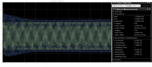
Figure 18 Graph
of Aux. Voltages Results Without Fuzzy |
The results obtained on aux.voltages in a time range of 0 s- 0.4 s with a blue wave from 364.8 V decreased to 200 V. In a time range of 0.6 s-2s the aux.voltages were stable with a voltage of 180
V. Results on aux.voltages with an overshoot of 1.982% and a rise time of 4,634 ms.
|
|
|
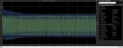
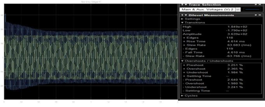
Figure 19 Aux.
Voltages Results Graph with Fuzzy |
The results obtained on aux.voltages in a time range of 0 s- 0.4 s with a blue wave from 363.9 V decreased to 200 V. In a time range of 0.6 s-2s the aux.voltages were stable with a voltage of 184
V. Results on aux.voltages with an overshoot of 2,35% and a rise time of 4,614 ms.
PID Simulation Results
|
|
|
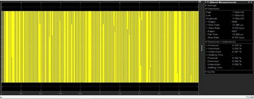
Figure 20 PID
Result Graph |
The results obtained on the PID in the 0.1 s-2s time range of 178.2V are stable. The results on the PID with an overshoot of 0.505% and a rise time of 31,885 microseconds.
Fuzzy PID Simulation Results
|
|
|
Figure 21 Fuzzy
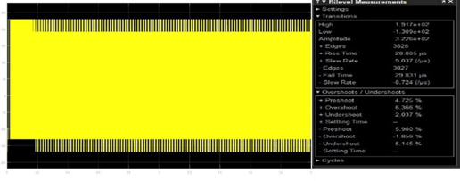
PID Results Graph |
The results obtained on the Fuzzy PID are 191.7 V, the highest and the lowest are 130.9 V. The results for the Fuzzy PID are 6.366% overshoot and a rise time of 28,805 microseconds.
Fuzzy Simulation Results
|
|
|
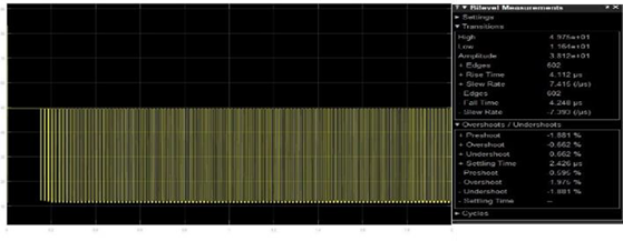
Figure 22 Graph
of Fuzzy Results |
The results obtained for fuzzy are 49.75 V, the highest and the lowest 11.64 V. The results for fuzzy overshoot are -0.662% and rise time is 4.112 microseconds.
|
Table 2 Simulation Results of All Data |
||||||
|
No |
Simulation Result |
|||||
|
|
No Fuzzy |
Overshoot |
Rise Time |
Fuzzy |
Overshoot |
Rise Time |
|
1 |
Main Current |
46.742% |
3.517 ms |
Main Current |
38.468% |
3.793 ms |
|
2 |
Aux. Current |
123.140% |
1.342 ms |
Aux. Current |
173.436% |
574.748 µs |
|
3 |
Main Voltage |
0.505% |
4.849 ms |
Main Voltage |
0.505% |
4.849 ms |
|
4 |
Aux. Voltage |
1.982% |
4.634 ms |
Aux. Voltage |
2.365% |
4.614 ms |
|
5 |
Load & Electromag Torque |
- |
- |
Load & Electromag Torque |
- |
- |
|
6 |
Rotor Speed |
0.505% |
346.111 ms |
Rotor Speed |
0.505% |
346.605 ms |
|
7 |
PID |
0.505% |
31.885 µs |
|||
|
8 |
Fuzzy PID |
6.366% |
28.805 µs |
|||
|
9 |
Fuzzy |
-0.662% |
4.112 µs |
|||
5. CONCLUSIONS
The design of a single-phase main and auxiliary winding motor speed control system with fuzzy logic has been able to show the main and auxiliary winding motor speed performance well. The overshoot on the fuzzy logic speed controller is smaller than the PID, which is 38.468%, the rise time is 3,793 ms at the main current. The value of the motor speed formed with PID control and fuzzy logic, the rotor speed with fuzzy is the same as that without using fuzzy of 1785 rpm with the same overshoot and fuzzy rise time value of 346,605 ms and the value of rise time without fuzzy of 346,111 ms. The results obtained in the Main current without fuzzy of 2.2 A, main current with fuzzy of 2.2 A, aux. Current without fuzzy is 1.6 A, aux. Current with fuzzy 1.9 A, load and elctromag torque without fuzzy no value, load and elctromag torque with fuzzy no value, main voltage without fuzzy 154 V, main voltage with fuzzy 154 V, aux. Voltage without fuzzy 180 V, aux. Voltage with fuzzy is 184 V, rotor speed without fuzzy is 1785 rpm, rotor speed with fuzzy is 1785 rpm.
REFERENCES
A. Faizal and V. D. Sinta, (2018) "Design of Single Phase Main and Auxiliary Winding Motor Speed Control in Centrifugal Machines With Second Order Viteckova Model Approach Using Hybrid Fuzzy-Smc Method," J. Sains, Teknol. and Ind., vol. 15, no. 2, pp. 138-143. Retrieved from https://doi.org/10.24014/sitekin.v15i2.5116
C. Ning, (2016)"Kalman filtering speed estimation of vector control for induction motor drives," IEEE Int. conf. Power System. Technol. POWERCON 2016. Retrieved from https://doi.org/10.1109/POWERCON.2016.7753864
D. R. Irawan, G. M. C. Mangindaan, D. Ph, and L. S. Patras, (2016) "Stability Analysis Motor Speed Main and auxiliary winding 3 Phase Based 80-86,
D. Sasmita, A. Pambudi, M. Sarwoko, E. Kurniawan, F. T. Elektro, and U. Telkom, (2016) "Control of Single Phase Main and auxiliary winding motors," J. Investigator. and Pemb. Telecom. Control, Computer, Electrical. and Electron., vol. 1, pp.76-84.
E. Wahjono, (2015) "Main and auxiliary winding motor speed regulation as" Electric Car Drive With Direct Torque Based Fuzzy Logic Controller Control," J. Ilm. Mikrotek, vol. 1, no. 3, pp. 136-144.
F. Arvianto and M. Rameli, (2017) "Single Phase Main and Auxiliary Winding Motor Speed Control Using PID Self-Tuning-Based Flux Vector Control Method," J. Tech. ITS, vol. 6, no. 2. Retrieved from https://doi.org/10.12962/j23373539.v6i2.25079
F. M. W. Fatih Mutamimul Wildan, (2016) "Main Motor Speed Regulation System and auxiliary winding Single Phase Using PIDD Based Controller Genetic Algorithm," Kinetics, vol. 1, no. 1, pp. 23-32. Retrieved from https://doi.org/10.22219/kinetik.v1i1.14
F. Yusivar and N. Avianto Wicaksono, (2016) "Main and auxiliary machine simulation winding Without Speed Sensor Using Vector Orientation Controller," J. Nas. Tek. Electrical and Technol. Inf., vol. 4, no. 4. Retrieved from https://doi.org/10.22146/jnteti.v4i4.171
L. Wang, S. Chai, D. Yoo, L. Gan, and K. Ng, (2015) PIDD and Predictive Control of Electrical Drives and Power Converters using MATLAB/Simulink. Singapore: John Wiley & Sons Singapore Pte. Ltd. Retrieved from https://doi.org/10.1002/9781118339459
M. S. A. Sari, H. Suyono, and A. Lomi, (2021) "Analysis of Motor Speed Control Main and auxiliary winding 3 Phase with Direct Torque Control Method (DTC) PIDD Based Control," vol. 8, no. 2, pp. 70-77.
N. Evalina and A. A. Zulfikar, (2018) "Adjusting the Rotation Speed of 3 Phase Main and auxiliary winding Motors Using a Programmable Logic Controller," J. Electr. Technol., vol. 3, no. 2, pp. 73-80.
R. Gunawan, F. Yusivar, W. Wahab, and Z. A. Kadir, (2010) "Design of Single Phase Main and Auxiliary Winding Motor Without Speed Sensor With Current Vector Controller And Full And Reduced Observer On The Dq Axis," MAKARA Technol. Ser., vol. 10, no. 1, pp. 34-39. Retrieved from https://doi.org/10.7454/mst.v10i1.408
 This work is licensed under a: Creative Commons Attribution 4.0 International License
© Granthaalayah 2014-2021. All Rights Reserved.