
ENERGY BALANCE ANALYSIS BETWEEN ENERGY CONSUMED FOR THE COMPRESSION OF ATMOSPHERIC AIR UP TO 200 BAR, AND THE ENERGY PRODUCED FROM ITS EXPANSION DOWN TO ATMOSPHERIC PRESSURE ON NICHOLAS PITTAS’ PATENT ABOUT STORAGE AND CONTINUOUS PRODUCTION ENERGY SYSTEM
Abstract
This paper provides the theoretical foundation the patents (Pat, ), (Pat, ) of Nicholas Pittas related to storage and continuous production of energy via compressed air. Specifically, the energy balance between consumed energy, used for the compression of atmospheric air to high pressure and heat production within a specific number of stages, and the energy produced during the expansion of compressed air to atmospheric pressure. The heat produced is transported, via a thermal vector, to the expansion process to prevent ice formation in the expander.
Keywords
Storage Energy, Intermittency, Compress Air, High Density Energy, Heat Transfer, Storage Tanks, Heat Exchanger, Compressor High Pressure, Expander
INTRODUCTION
In the past decades, Europe has relied on fossilfuel-based energy generation to cover energy demand. Due to the environmental problems coming by burning fossil fuels, the world started to turn at renewable energy sources (RES), as a potential solution, to replace the environmentally harmful fossil fuels. However, RES, due to their stochastic nature (often and unpredictable intermittencies), cannot respond to the energy demand the same way as fossil fuels do.To solve the problem of intermittency the industrial need for storage system was created. This way RES energy can be stored, and consequently smoothed, and distributed according to demand as the convention systems do. Storage systems used nowadays are chemical, electrochemical, electrical, mechanical, or thermal. All these systems try to tackle efficiently the above problem and they achieve it to a certain degree.
Energy storage technologies allow us to store excess energy and discharge it when there is too little generation or too much demand. They provide flexibility at different time-scales – seconds/minutes, hours, weeks, and even months.
Storage can help consumers increase self-consumption of solar electricity, or to generate value by providing flexibility to the system.
Industrial consumers can install storage to reduce consumption peaks, and to provide back-up power in case of black-out. In addition, storage of any level can offer system services, safeguarding the secure and efficient operation of the electricity system.
Storage can help defer costly investments in transmission and distribution infrastructure, extending the lifetime of existing assets and helping grids function more efficiently.
Energy storage deployment could facilitate the electrification heating and cooling sectors, and support the roll-out of very fast charging infrastructureσ for electric vehicles, particularly in areas with weak grids.
Energy storage can store surplus energy from intermittent renewable sources, such as solar PV and wind power, until it is required – allowing therefore the integration of additional renewable energy into the system.
Different energy storage systems – centralized and decentralized – consider different technological possibilities, which EASE organizes in 5 energy storage classes: chemical, electrochemical, electrical, mechanical and thermal.
The state of art of storage of energy are batteries (electrochemical storage of energy) but they can impact heavily the environment. In 2017, the potential of lithium-ion batteries captured the headlines when famous entrepreneur made a $50 million bet that his company could build a 120 MWh battery storage in South Australia in under 100 days – if not, then the company would charge nothing for its construction, (, ). The state had been crippled by power shortages and took him up on his wager. The company delivered in 60 days and the result is the largest battery storage facility in the world, which supports and stabilizes existing electricity supplies in the state. However, although lithium-ion batteries seem to be the main contender for solving the renewable energy storage conundrum, they do have drawbacks. Lithium is relatively rare and its supply is controlled, in effect, by a handful of mining companies. Cobalt, which is needed for the cathode, is both toxic and rarer still. Although battery prices have dropped recently and they are a quick responder when needed, batteries have relatively short lifecycles (between five and ten years), they degrade and they have a realistic economic limit of about four hours for harnessing large amounts of power.
In this paper, the thermodynamic analysis of an innovative adiabatic compressed air storage system (ACAES) is presented. Air is compressed and stored, and then it expands producing electrical energy. A thermal vector, water or oil, is used to absorb heat produced during the compression and heats up the air before expanding where temperature drop can become dangerous.
A lot of relative research activities have been done on the development of ACAES but none of them reached the benefits of the proposed system, such as is LightSail Energy Storage (, ), which failed despite the huge funding, or ADELE, Adiabatic Compressed-Air Energy Storage for Electricity Supply (, ), which used underground cavers setting storage limitations and difficulties. Projects of this caliber can be found also in CORDIS, such as Design Study for the European Underground Research Infra-structure (, ) related to Advanced Adiabatic Compressed Air Energy Storage which also relies on caverns, or Advanced adiabatic compressed air energy storage (AA-CAES) (, 2002) with low efficiency around 70%. The above examples prove the innovations contained into the proposed system.
ΑNALYSIS
The target is to obtain high temperature for the diathermic oil and/or saturated water over to 230 οC. In this way we can heat the compressed air exiting air tank, before entering into turbine, otherwise phenomena of icing will occur.
Further we choose the final value of compression to be 200 bar. In this way, we will have high energy density because 1 m3 of air at 200 bar can produce about 30 kWh.
As a first estimation, to find the optimum solution, we choose 4 stages for the compression.
Work Transfer Components
Basic Assumptions
Atmospheric air has a temperature of Tair= 20oC = 293K, specific heat at constant pressure cp,air=1.006 kJ/kg/K(or oC) and heat capacity ratio γ=1.4, a typical polytropic efficiency of a compressor and expander is ηpc= ηpt=0.85 and a typical efficiency of a heat exchanger is ηHx 0.90.
The compression has 4 stages, each one delivers a compression ratio:
If the exhaust air temperature T2is 200oC (473 K) the inlet temperature T1 of air is

In Figure 1 the above process, 1-2, is depicted. The process 1-3 is the isentropic 1-2 process.
Before the air enters the next compression stage, it is cooled in a heat exchanger with cold water, Figure 2 .
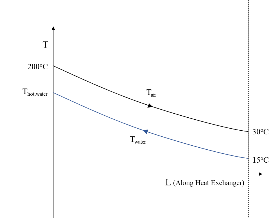
If the water enters with temperature Tcold,water=15οC it exits with temperature:
The work done on each compressor stage per kgair of compressed air is given by:
Hence the compressor will absorb
The mass of water required for the intercooling of air in each stage will be equal to:
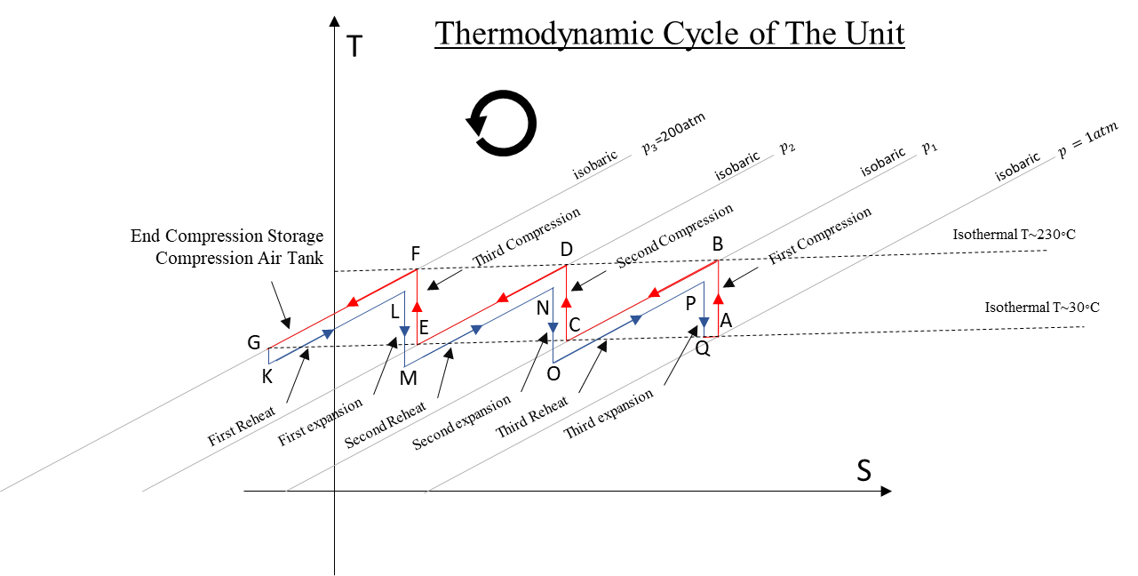
After four stages of compression, air has been stores at 200 bar and 30oC, and hot water at 182oC has been produced and stored as well.
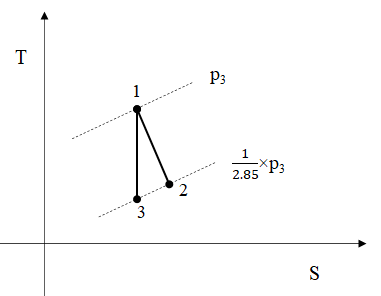

Now the analysis of the expansion per stage, Figure 3 , and the corresponding reheat, Figure 4 , follows. The expansion 1-3 is the isentropic of 1-2 expansion. It must be noted that the temperature of stored air will be taken as 20oC due to losses and the temperature of water after reheating the air is assumed to reach the temperature of air 20oC, Figure 4
So, the temperature after reheat is calculated to be:
For the reheat per expansion stage we need mwater kg of water per kgair :
Hence air enters the expander with T1=Thot,air.We set the temperature of air after the expansion stage to be T2=30oC=303.15K andwe estimate the pressure ratio of the stage of the expander:
For a full expansion of we need Nt stages so that:
So, the pressure ratio of every stage of the expander is:
The air temperature at the exit of the stage is calculated below:
Assuming that every stage has the same inlet and outlet conditions, the work output of the 4 expander stages will be:
So, the efficiency of the unit is
Of course, we have assumed zero heat losses and have neglected the extra work by the remaining hot water.
During compression 4×0.246 = 0.984 kgwaterof water are produced, while in the expander 4×0.202 = 0.808 kgwater are consumed for reheat. In other words, the entire process will produce a surplus of 0.176 kgwater per kgair.
This is to be used for energy production. Essentially, the saturated water surplus is available energy which if it is not used, it will be lost. Injecting this amount of steam in the last stage of the expander an additional amount of work per is produced equal to:
h2=2830 kJ/kg is the enthalpy of water at 3.76 bar and 165.8 oC
and h1=2552.25 kJ/kg is the enthalpy of saturated steam at 30 oC
This results to
So, the overall efficient of the system including water surplus becomes:
Algorithm
An algorithm has been built in Excel to calculate with better precision the performance of the system for different number of compression and expansion stages (1 to 10). The process is described below.
Our goal is to compress atmospheric air from environment conditions up to 200 bars. The properties of air are assumed to be temperature Tatm=20oC, specific heat at constant pressure cp,air=1.006 kJ/kg/K(or oC) and heat capacity ratio γ=1.4.
Compression Phase
Below the steps for the calculation of compression procedures are presented.
STEP 1. Pressure ratio of compressor stages:
Defining as Nc the number of the stages of the compressor we calculate the pressure ratio, Πc,s, of each stage using the expression:
STEP 2. Air temperature after compression:
If each stage has a polytropic efficiency ηpc of 0.85 and intel temperature T1=Tatm=20oC, the temperature of air after the compression, T2, is calculated:
It must be noted that the temperature T1=Tatm=20oC is used only for the first stage of the compressor with Nc stages that air is coming directly form the environment.
STEP 3. Compression work:
The work per kg of air, Wcomp,s/mair, needed for the compression of the first stage is calculated according to:
STEP 4. Cooling process:
After the first compression the temperature of air has risen from T1 to T2. Before the second compression (in case Nc> 1), the air passes through a heat exchanger to cool down to Tcold,air=30oC. The heat exchanger uses water at Tcold,water=15oC and its efficiency is assumed to be ηΗx=0.9. The specific heat of water at constant pressure is cp,water=4.18 kJ/kg/K(or oC).
According to the above we calculate the temperature of water after passes through the heat exchanger Thot,waterand air inserts at Thot,air=T2:
the ratio of mass of water per mass of air, mwater,c,s/mairrequired is:
STEP 5. Calculations for the remaining stages:
To find the above values for all the remain stages, we repeat the steps 2 to 4 using instead of T1=Tatm=20oC the temperature of air at the exit of the heat exchanger Τ1= Tcold,air=30oC.
STEP 6. Total consumed energy and water used in compression phase:
Finally, we complete the calculations of compression by summing up the power consumed by every stage (Wcomp,s)i and the ratio of masses (mwater,c,s/mair)i to find the total work needed for compression, Wcomp, and the total water needed for cooling, mwater,c/mair.
Expansion Phase
After the above procedure, compressed air at 200 bar and hot water have been stored. Using the values calculated during the compression we follow the steps below to estimate the performance of expansion.
STEP 1. Reheat process:
Before entering the first expansion stage, air is reheated using the heated water and a heat exchanger with the same characteristics as before. Water enters with the temperature Thot,water of the compression phase, as described above, and the temperature of stored air is assumed to be Tcold,air=Tstored=20oC. We have assumed that the temperature has dropped due to thermal losses. Using the same expression as above we calculate the reheated air temperature Thot,air:
and the mass ratio mwater,rh,s/mair required for this process:
STEP 2. Calculating expansion stages:
Ideally, we want the temperature of air after the expansion to be around T2=30oC. To achieve that, we calculate the adequate pressure ratio, Πe,s, of each expansion stage,with inlet temperature the one exiting from the heat exchanger T1= Thot,air. Again, we assume that each expansion stage has efficiency ηpt:
To have a total pressure ratio of 200, the number of the expansion stages are found with the expression:
Eventually Nt is a rational number. To have physical meaning we round up Nt to the nearest natural number, e.g., 3.48541 → 4. It must be noted that by following this process the number of expansion stages is the same with that of compression.
STEP 3. Pressure ratio of expansion stages:
Having defined the number of expansion stages we calculate their pressure ratio, Πe,s to achieve total pressure ratio 200:1.
STEP 4. Air temperature after expansion:
Knowing Πe,s and the inlet temperature of air after reheat T1 we calculate the outlet temperature of air T2:
STEP 5. Produced work:
As we did is the case of compression, we calculate the work produced in every stage of the expander per kg of air:
STEP 6. Calculations for the remaining stages:
To calculate the performance of the rest stages we repeat the steps 1, 4 and 5. At the reheat process before entering stage i, step 1, instead of Tcold,air we take the outlet temperature T2 of air of the previous expander stage (i-1), of course to do this Nc ≥ 2. All the other values stay the same.
It must be noted that when i ≥ 4 the outlet temperature T2 is almost constant for the rest of the stages. So, the performance of stage 5…, Nt is the same with that of stage 4 and no further calculations are necessary.
STEP 7. Total produced energy and water used in expansion phase:
Once more, we complete the calculations of expansion by summing up the power produced at every stage (Wexp,s)i and the ratio of masses (mwater,rh,s/mair)i to find the total energy production, Wexp, and the total water needed for reheat, mwater,rh/mair.
Overall estimation of system performance
With the above calculation we have estimated the performance of compression and expansion for different number of compression and expansion stages. As it was described these numbers happen to be equal Nc= Nt=N.
The overall efficient of the system, for each number N, is calculated to be:
This is the efficiency of the system without using the surplus of water that is produced during the compression and expansion phase. This surplus is equal to:
This surplus of stored water has a considerable temperature of Thot,water and by inducing it into the last stage of the expansion more work is produced:
where h2 is the enthalpy of water at the inlet of the last stage and h1 at the outlet. It has been assumed that the water is at the region of gas state during these procedures.
Therefore, the efficiency including the work of surplus water is:
Results
In Figure 5 the efficiency of the overall system with surplus water is shown.
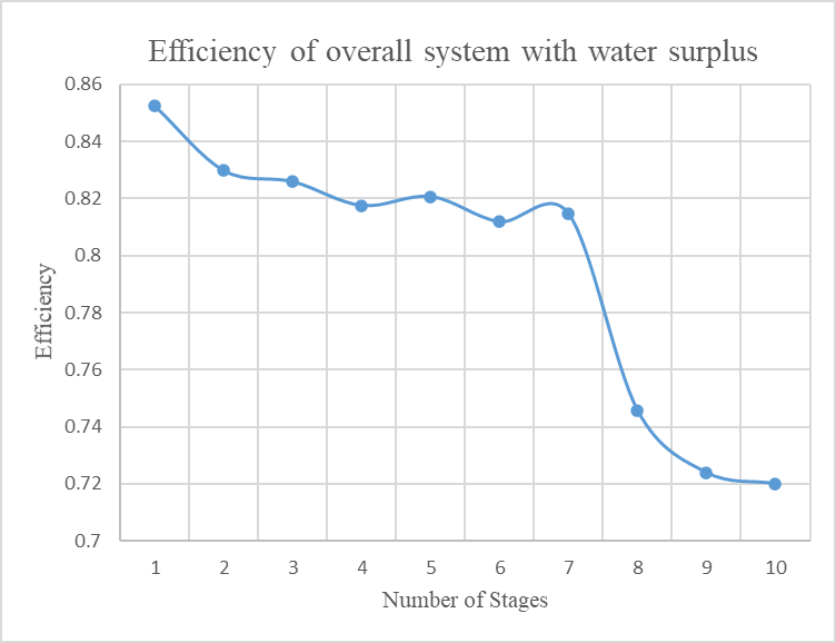
It is clear that the efficiency of the system maximizes as the number of stages decreases. However, the theoretical temperatures of air when one and two are used are very high (465oC and more) and this creates difficulties at technical level. For this reason, we choose as the optimum theoretical and technical solution to use three stages of compression and expansion for the operation of the system.
It must be noted that the efficiency using 4 stages is 81% according to algorithm instead of 79% that we found above. Thisisdueto the fact that the algorithm calculates the water mass needed for reheat using the temperature of air of the previous stage which is more than that of stored air, which means that less hot water has to be used to reheat the air. This results to more water surplus and consequently more produced energy.
According to the above theoretical analysis of the whole thermodynamic cycle of the system emerges that the surplus of water, or any other thermal vector used, increases when the number of compressor stages increases. At the same time, the potential to transfer thermal energy, produced during the compression and used to reheat the compressed air during expansion, decreases because the temperature of thermal vector decreases as the number of stages increases.
Consequently, the efficiency of the entire thermodynamic cycle decreases as the compression stages increase.
As it is documented with the above comparative assessment of the efficiency of the system, relating to reducing number of compression stages, it is inferred that the maximum efficiency of the whole system is achieved when 3 stages are used for the compression.
The area between the almost parallel lines of compression and expansion, which enclose the thermodynamic cycle, represent the total thermal losses during the operation of the system.
In the ideal case this area is zero, the total efficiency is 100% and the lines of the compression and expansion coincide.
The number of compressor stages per compressor, considering the ongoing technological feasibility and efficiency for the optimum solution of the system consisting of air compressors, high pressure tank and turboexpanders, cannot be any other than 3 stages.
The consequence of this choice is that the total water surplus of compression-expansion reduces to 0.18 kgwater/kgair instead of 0.242 kgwater/kgair in the case the compression stages were 4 (according to the algorithm). The surplus becomes even better if the number of stages increase further.
Using 3 compression stages the overall efficiency of the system reaches 82%. This also makes the construction of the system more conducive and brings further advantages.
All the above result to the construction of a long duration energy storage and energy production system of high efficiency, it is full green, it’s performancecannot be found in any other system, and it solves radically and simultaneously an energy and environmental problem.
The system analyzed here aims to bear the following advantages over all the existing energy storage systems:
-
Synchronous Inertia: Maintaining the grid’s intrinsic resistance to frequency deviation.
-
Dynamic Voltage Support: Supporting a grid with increasing levels of distributed energy resources and new types of demand.
-
Fast Fault Current: Actively responding to frequency and load deviations.
-
Synchronizing and Damping torque: Capability to limit and control the rate of change of voltage angle in transient conditions.
-
Low energy related cost: Cost effective technology for long duration storage applications.
CONFLICT OF INTEREST STATEMENT
Manuscript title: Energy balance between energy consumed for the compression of atmospheric air up to 200 bar, using a specific number of stages, and the energy produced from its expansion down to atmospheric pressure, again using a specific number of stages. This analysis constitutes the theoretical foundation of the patents of Nicholas Pittas (Pat, ), (Pat, ) and of the methodology which is described in them for the storage and continuous production of energy. This analysis proves the high efficiency of the system.
The authors whose names are listed immediately below certify that they have NO affiliations with or involvement in any organization or entity with any financial interest (such as honoraria; educational grants; participation in speakers’ bureaus; membership, employment, consultancies, stock ownership, or other equity interest; and expert testimony or patent-licensing arrangements), or non-financial interest (such as personal or professional relationships, affiliations, knowledge or beliefs) in the subject matter or materials discussed in this manuscript.
Author names: Ncholas Pittas
DATA AVAILABILITY STATEMENT
The datasets generated during and/or analysed during the current study are available from the corresponding author on reasonable request.
