
VALIDATION OF EQUATIONS LECKNER FOR CALCULATE THE EMISSIVITY OF GAS COMBUSTION MIXTURE OBTAINED FROM THE COMPARATION WITH THE METHOD OF HOTTEL AND THE APPLICATION ON AN INDUSTRIAL THREE BED REGENERATIVE CHAMBER COMBUSTION UNIT
Abstract
This paper investigates the validity of the LECKNER relationsproposed to calculate the emissivity of mixture of gas combustion in comparation by H. Hottel and R. J. Tucker method for enclosures with surfaces exposed to significant thermal radiation. The analysis is focused on a specific combustion chamber in a three-bed regenerative oxidizer and calculates the coefficient of absorption and the corresponding thermal irradiation flux exchanges among the hot wall surfaces of the chamber. The temperature distribution and the initial composition of the gaseous mixture at the inlet plane were assumed known.
Keywords
Gas Mixtureemissivity, Radiation, Combustion Chamber, Thermal Three Bed Oxidizer, Coefficient Absorption
INTRODUCTION
By comparing the online measurements of the chamber wall temperatures in the specific plant under consideration, the method proposed by Professor H. Hottel (Hottel, 1967) was validated for chamber sizes comparable to the one employed in this plant.
The analysis of the waste gas composition involved the calculation of the component’spartial pressures through Dalton's law.
It was assumed that the waste gas components (vapor and carbon dioxide) were grey and followed Lambert's law.
The model of this mixture representing the waste gas assumed a composition of vapor, CO2 and a non-reacting gas.
The energy exchange among two surfaces of the chamber were evaluated with the help of the beam attenuation constants provided by H. Hottel (Hottel, 1967), These data were supplied in the form of diagrams as functions of the parameter pL, where p represents the partial pressure of either the water vapor or the carbon dioxide, and the gaseous mixture temperature. The length L represents the mean beam length between the two surfaces under consideration. The correct value of the attenuation parameter was evaluated through a regression analysis from the experimental data provided by these graphs at a temperature 750oC. The weak influence of the overlapping interaction of the emission wavelengths of water vapor and carbon dioxide were added to the above analysis. A final correction was introduced for the fact that the chamber pressure was sub-atmospheric. These experimental data were next inserted into the conservation equations for the energy exchanged among any two surfaces. These equations were essentially those provided by R.J. Tucker (Tucker, 19851986). The details of the theoretical model employed for the energy exchange analysis will be discussed below.
This paper compares the values of the thermal coefficients of heat absorption obtained using the classical HOTTEL method and the values from the proposed LECKNER equation necessary to calculate the thermal fluxes in the combustion chamber applied to an operating plant. for neutralizing gaseous pollutants with simultaneous energy recovery.
The calculation of the absorption coefficients of heat radiation is necessary to calculate the thermal radiation between the surfaces, between the surfaces and volumes of the gas mixture and between the volumes of gases into which the inner surface is divided and the volume of the combustion chamber by diagrams of HOTTEL or the polynomials of J. TUCKER.
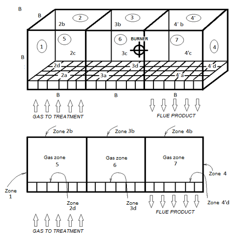
The schematic depicted of the combustion chamber is shown below, Figure 1 , and this element is an integral part of the gas pollutant heat processor with simultaneous energy recovery and it's the upper part of it.
ΑNALYSIS
DETERMINATION OF THE MEAN BEAM LENGTH OF THE COMBUSTION CHAMBER
The evaluation of the elemental partial pressures was based upon Dalton’s law and the measured gaseous concentrations. These pressures were combined with the mean beam lengths of the radiation exchanges among the chamber wall surfaces in order to evaluate the free parameter known as “the wave length” p x L (atm x ft).
The prediction of the average spatial distribution of the gas temperatures inside the chamber space and the temperature and heat-flux distribution on the walls of the combustion chamber whose geometry and size as well as the enclosed gas properties are specified is presented in the following analysis:
It was assumed that the gaseous mixture inside the chamber was equivalent to a mixture of two grey gases (Carbon Dioxide (CO2) and water steam (H2O)) as well as a neutral gas (Nitrogen (N2)). The total emissivity of this gaseous mixture may be evaluated by the following relationship:
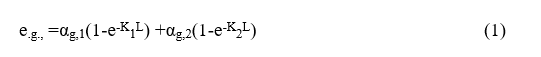
Were
egi=emissivity
agi=absorption coefficient
Ki =attenuation coefficient
L =mean beam length
The emissivity for each of the active exhaust gases i (water vapor (i=1) and carbon dioxide (i=2)) was taken from the data provided in Reference (Hottel, 1967) as functions of the corresponding values of the wavelength parameters pwLm and pco2Lm.
The actual in situ measurements of the gaseous and the wall temperatures were conducted by a specialized company (ENCO LTD), which provided as well the gaseous concentrations and the corresponding partial pressures for the running conditions of the facility. As reported above, these data provided the basis for the evaluation of the free parameters (piL) needed for the final evaluation of the gaseous emissivity for an assumed constant gaseous temperature equal to 750oC inside the entire chamber. The emissivity evaluation was based on the experimental data provided by the relevant charts in .11 (page 232), Fig 6.9 (page 229), Fig. 6.12 (page 233) of Reference (Hottel, 1967), with the constant temperature of the enclosed gases inside the chamber transformed into the Rankine scale, i.e. T=1841oRa.Actually, the emissivity parameter was evaluated by the following relationship:

whereΔε = The wavelength overlap parameter
These charts apply for a chamber pressurized to a pressure equal to that of the surrounding atmosphere (i.e., 1 atm). When the chamber pressure differs from the atmospheric (in the plant under consideration it was regulated so that it was maintained steady at a magnitude of 0.4 atm) it was necessary to readjust the emissivities determined above by introducing correction coefficients CH 2 O and CCO 2, which multiplied the corresponding two emissivities.
The determination of the correction factors CH 2 O and CCO 2 was based on experimental data provided in charts (Fig.13.56 and Fig13.57 in Rathore, Kapuno (, 2011)).
Τhe gas absorptivity and emissivity of the entire mixture were evaluated in a similar manner as the weighted sum of the corresponding contributions for each particular grey gas, i.e.
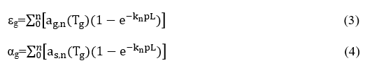
Were
εg=emissivity
ag=coefficient of gas absorption
as=coefficient of surface absorption
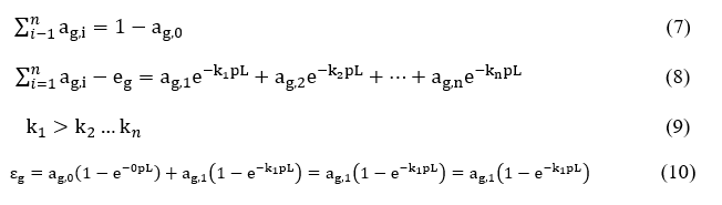
The emissivity-pL relationship for the gaseous mixture may be depicted as the weighted sum of the particular contributions of the gray gases participating in it and this relationship can be expressed as

In other words,εg is an increasing function of pL with an upper limit unity for a large value of the pL parameter. In this limit

Hence all εg values are positive.
For k = 0 there exists no active grey gas component inside the mixture. For non-zero values of k, it may be shown that
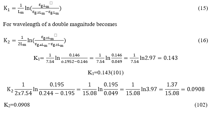
Defining the pLm and 2pLm values in the above equation, results into the following relations
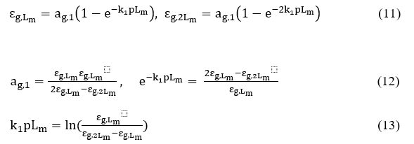
by replacing the product kip = Ki

For the chamber under consideration, K1becomes

For wavelength of a double magnitude
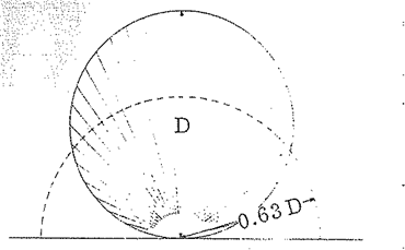
The mean beam length was defined by H. Hottel (Hottel, 1967)to represent the radius of an equivalent hemisphere so that the incident radiation flow at the center of the hemispherical base equals the average radiation flux incident to the surfaces surrounding the gas volume. According to this Reference this flux may be given by (Fig. 7.1, page 257) H. Hottel (Hottel, 1967))

APPLICATION
Τhe determination of the mean beam length for every combustion chamber is fundamental for the calculation of the heat radiation exchange between the isothermal zones on which the combustion chamber is divided. This representation allows for the implementation of the theory of thermal zones. The volume of the combustion chamber under consideration is equal to
We consider the dimensions of the interior walls of the combustion chamber
L = 9.15m = 30 ft. Elongated and the other two sides each 3.05 m = 10ft.
So, the geometric volume of the combustion chamber is

And the area surrounding it equals

The mean beam length is obtained

This empirical formula applies to rectangular shaped combustion chambers and so finallyLm = 7.54ft, and because the percentage of LPG combustion gases in the combustion chamber during the passage of 22,000 Nm3/h was measured to contain19.8% Ο2, 0.6% CO2, 6% H2O.
CALCULATION EMISSIONS, OF WATER VAPOR AND CO2 AND ITS MIXTURE IN THE COMBUSTION CHAMBER AND CALCULATION OF ABSORPTION COEFFICIENTS
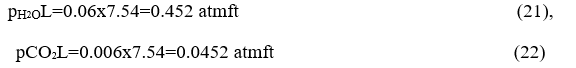
Dalton's law gives the partial pressures and multiplying the mean beam length corresponding to the orbit to obtain the necessary pL parameters for each component of the waste gas mixture to calculate the corresponding CO2 and water vapor emissions.
We look at Hottel's tables for CO2 and water vapor emission with PL parameter.
The tables are applicable to radiant gases at atmospheric pressure. If they do vary the atmospheric pressure then the corrective factor must be taken into account.
We consider the mixture of constituent gases as a gray gas following Lambert's law so as to reduce the emission calculations in the existing diagrams.
We're counting now
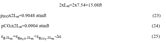
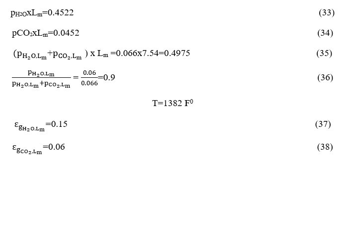
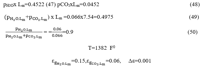
The water vapor emission is calculated from Chart 6-1 and equals
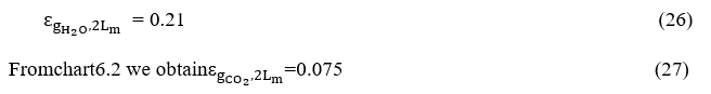
From chart 6.3 become Δε where we have

become the value of ordinates is equal to 0.9.
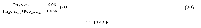
The parameter value in the curves with a corresponding trajectory is calculated by defining the following product:
Replacing the values ofΔεand the = 0.202 of =0.075 becomes

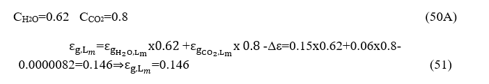
Because the combustion chamber is at a 0.4 atm pressure, we must multiply each of the terms H2O and CO2 by the corresponding correction coefficients resulting from diagrams 8 and 9 (Source Engineering Heat Transfer / Rathore, KapunoFig.13.56, Fig.13.57, Fig.13, respectively, in which the path length is expressed by atm.m rather than atm.ft (as depicted in Fig. 6-10 Hottel) by one atmosphere at a pressure of 0.4 atm.
Further we have

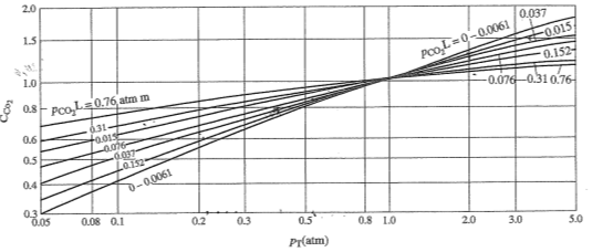
From the diagrams 8 and 9 and taking into account
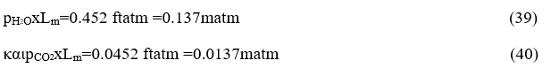
we obtain
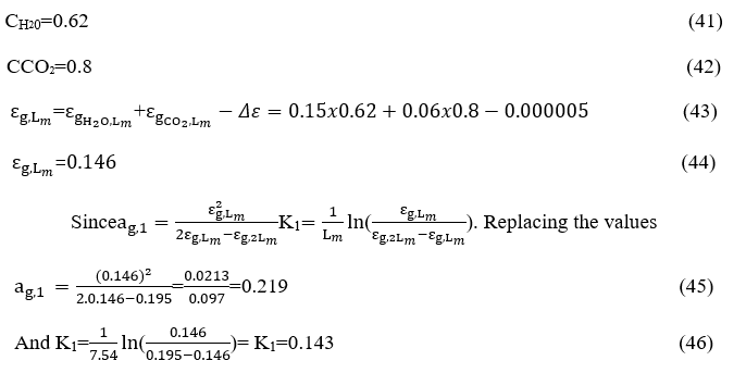
It should be noted that the overall emissivity of the gas mixture is less than the sum of the individual emissions (as if each of the two gases were emitted separately) by a correction factor Δε, because each gas behaves as a duplicate in areas between 2.7 m and 15m. Thus, the total radiation is reduced and this correction factor is drastically reduced at temperatures above 1200oK. And so, because
From the diagrams depicted on the Figures4και5we obtain
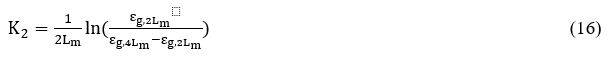
By similar way how calculated K1we will calculate Κ2andαg,2.
And because
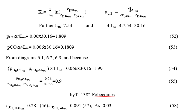
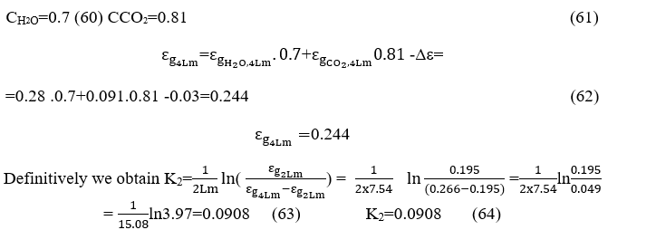
From diagrams depicted on the figure8 and 9 because the pressure is 0.4 atm becomes

and so, we obtain
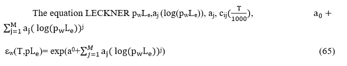
CALCULATION OF ABSORPTION COEFFICIENTS BY LECKNER
Another way to calculate the absorption coefficients with a large approximation is given algebraically by Leckner's relations.
In order to calculate the vapor emissions as well as the CO2 and therefore the absorption coefficients we will use another algebraic way of calculating the Leckner equation.
Coefficients of the LECKNER equation for water vapor and CO2
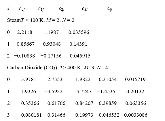
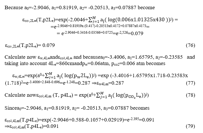
We consider that N2 has no significant emissivity, so we will calculate according to the model the water vapor and carbon dioxide emissivities.
cij( )iwhereΤmeasuredbyΚ0, pw partial pressure of vapor measured by bar and the wave length Le by cm. Int his case Le=7.54ft/3.05ft/m=2.15m=215cmand 1atm=1,01325bar

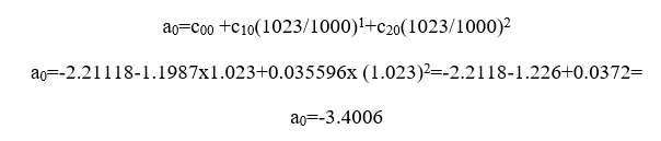
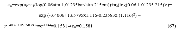
Calculate now εwthe temperature of combustion chamber is 750 0C= 1023 0K
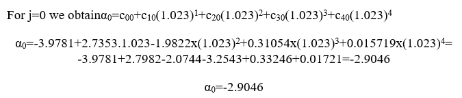
For j=0
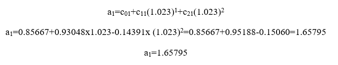
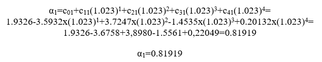
For j=1
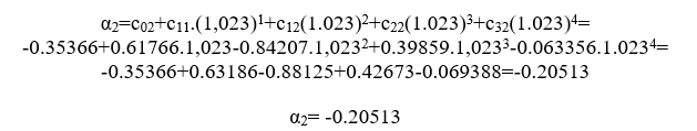
For j=2
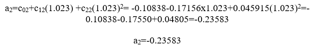
consequently becomes
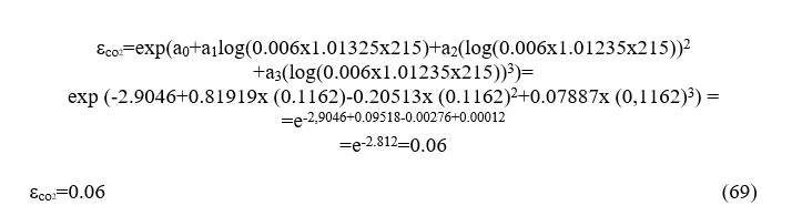
Calculate now the emissivity εco 2
For j=1 we have
For j=2 we have
For j=3 we have
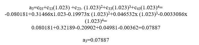

we have
Calculate now Δε from the Leckner relations.
From Leck nerrelation we have
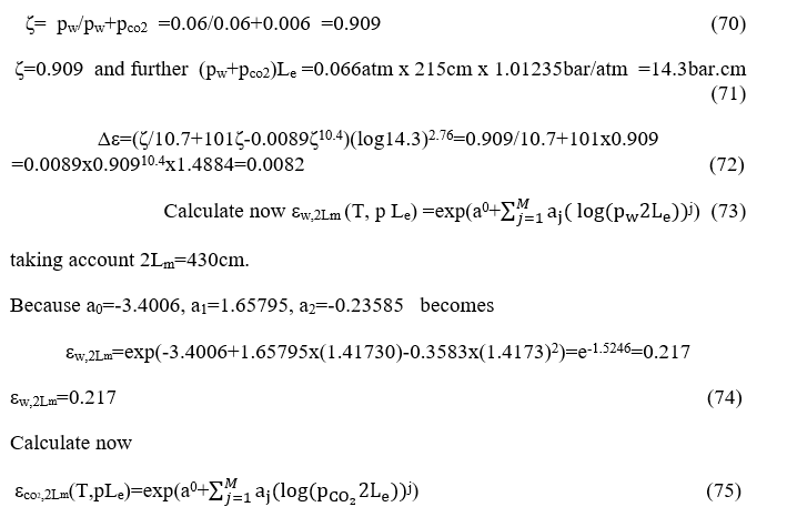
We now calculate the final emissivities taking into account the correction factors because the combustion chamber operates at a pressure of 0.4 atm. For these wavelengths.
For the wave length Lm=2.15,2Lm,4Lm corresponding
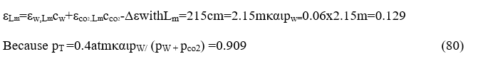
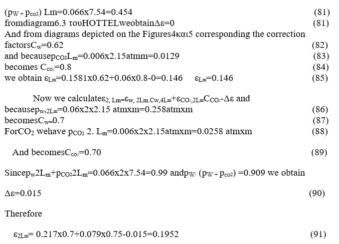
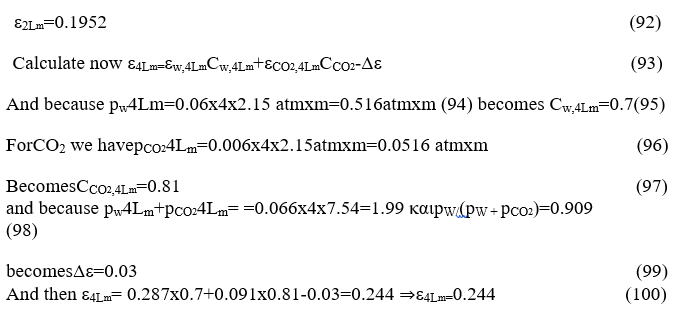
Replacing the values εg,L m , εg,2L m, εg,4L minto the relations (15) and (16)
CONCLUSIONS
From the above calculus becomes thesamevaluesΚ1, Κ2for attenuation coefficients using the method of HOTTEL or the relations of LECKNER. In other words, the validation of the LECKNER proposal relations.
DATA AVAILABILITY STATEMENT
The datasets generated during and/or analysed during the current study are available from the corresponding author on reasonable request.
DECLARATIONS
CONFLICTS OF INTEREST/COMPETING INTERESTS
The authors whose names are listed immediately below certify that they have NO affiliations with or involvement in any organization or entity with any financial interest (such as honoraria; educational grants; participation in speakers’ bureaus; membership, employment, consultancies, stock ownership, or other equity interest; and expert testimony or patent-licensing arrangements), or non-financial interest (such as personal or professional relationships, affiliations, knowledge or beliefs) in the subject matter or materials discussed in this manuscript.
AVAILABILITY OF DATA AND MATERIAL
Available after reasonable request.
CODE AVAILABILITY
Not applicable
AUTHORS' CONTRIBUTIONS
Conceptualization: Nicholas Pittas; Methodology: Nicholas Pittas; Formal analysis and investigation: Nicholas Pittas; Writing - original draft preparation: Nicholas Pittas; Writing - review and editing: Nicholas Pittas, Demos P. Georgiou, Vasileios Moutsios, IriniMuravieva; Funding acquisition: Nicholas Pittas; Resources: Nicholas Pittas; Supervision: Demos P. Georgiou.
ETHICS APPROVAL
Not applicable/The suggested paperdoes not enter any ethics issues.
CONSENT TO PARTICIPATE
Nicholas Pittas, Demos P. Georgiou, Vasileios Moutsios and IriniMuravieva have consented to participate in this research study.
CONSENT FOR PUBLICATION
Nicholas Pittas, Demos P. Georgiou, Vasileios Moutsios and IriniMuravieva have consented to publish this research study.
