
|
|
|
|
Investigation of a Compact Microstrip Patch Antenna for Wireless Communications
Poornanand Dubey 1
1 Assistant
Professor, Department of Electronics & Communication Baderia Global
Institute of Engineering & Management, Jabalpur (M.P.), India
|
|
ABSTRACT |
||
|
Indicates the
comparative characterization of a microstrip patch antenna array with
defective geostructure for biomedical application.
Compared to traditional antennas, various antennas have advantages in terms
of small dimension, low volume, light weight, ease
of construction, as well as low interference and good performance after which
all understudies use mobile phones to go to classes and educators to take web
classes use cell phones. For the above use we need a
fast 5G organization with high Bandwidth. This paper proposes a reduced 5G
Microstrip patch antenna with DGS structure for better approach for 5G wireless
applications. The DGS idea is widely used to improve the radiation properties
of the reception device. In the proposed work, a 5G Microstrip patch antenna
with 0.4mm thickness FR4 substrate and Dielectric
constant (r) of 4.4 is planned |
||||
|
Received 08 June 2024 Accepted 10 July 2024 Published 31 July 2024 DOI 10.29121/ijetmr.v11.i7.2024.1531 Funding: This research
received no specific grant from any funding agency in the public, commercial,
or not-for-profit sectors. Copyright: © 2024 The
Author(s). This work is licensed under a Creative Commons
Attribution 4.0 International License. With the
license CC-BY, authors retain the copyright, allowing anyone to download,
reuse, re-print, modify, distribute, and/or copy their contribution. The work
must be properly attributed to its author.
|
||||
|
Keywords: Microstrip
Patch Antenna, Dielectric Substrate, Bandwidth, Radiation Pattern |
||||


1. INTRODUCTION
Microstrip Patch Antenna A microstrip patch antenna is a type of microstrip antenna. This is the most common form of antenna. This barrier substrate consists of a conductive strip of any flat or flat geometry on one side, and the ground plane on the other Metallic strips are usually made of conductive materials such as copper, gold, tin, nickel, etc. The metal must be corrosion resistant Kasinathan (2017) patch can be any shape such as rectangular, circular rings and so on Microstrip patch antennas have low profile configurations and are capable of dual and triple frequencies These advantages make these antennas best suited for space and mobile applications. However, narrow bandwidth, low gain, and external radiation from the feed junction are its main disadvantages Khidre et al. (2016).
To overcome these limitations, these antennas can be loaded with more stubs, shorting pins and diodes to achieve compact dual-frequency operation, frequency agility and polarization control so these antennas in the commercial sector of industry especially GPS (Global Positioning System), SDARS (Satellite Digital Audio Radio). Service) and WLAN (Wireless Local Area Network). Antennas are an essential part of all devices that use radio waves that are finding more and more applications. They are used in radio broadcasting, broadcast television (TV), two-way radio, communication receivers, radar, mobile phones, satellite communications, garage door openers, Bluetooth-enabled devices, microphones, wireless networks, child monitors, and RFID tags in products [Sappal et al. (2018), Yang & Xie (2019)].
The microstrip antenna consists of a patch, substrate, and ground. The fine strip line feed is placed on the strip. This microstrip antenna is sometimes called an electromagnetically incorporated patch antenna. The microstrip patch is designed by analyzing the frequency, substrate and thickness and calculating the antenna dimension. Bandwidth can then be increased by using the appropriate type of feeding, and gain can be increased. Depending on the application, the band structure can be modified [Yu (2017),Geran & Amiri (2022)].
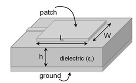
Figure 1
|
Figure 1 MPA with its Dimensions |
The shapes of the stripes are square, rectangular, circular, and hexagonal, etc. Microstrip patches have small profile flat and non-planar surfaces. Using new printed circuit board technology, they are simple and inexpensive to manufacture, and are mechanically robust [Gao et al. (2019)].
2. LITERATURE REVIE
Nitesh Jha et al. (2018), the simulation of the design of hexagonal (hexagonal) antennas of microstrip patches using edge cutting is discussed here. This antenna is fed using a probe feeder model. This is done using the IE3D electromagnetic simulator. The modified antenna generates radiation parameters such as propagation parameters (S-parameter), radiation pattern and voltage standing wave ratio (VSWR). The value of parameter S11 for parameter S was found to be <-10 dB at audible frequency from 0.9 GHz, 0.87 GHz to 0.90 GHz and the value of VSWR < 2 was found at the same frequencies The proposed antennas will be useful for wireless communication applications in the 900 MHz band
Gao, Xiang-Jun et al. (2018), in this paper, the radioactive patch is located on a Teflon substrate with a dielectric constant of 1. The coaxial feed method is used to feed an antenna of 50 ohm impedance This proposed antenna is -14 dBi at 3.65 GHz and -14 dBi at 5.765 GHz. 28 dBi raises the return loss. The computer simulation results show lower VSWR values in the 3.6-3.7 GHz and 5.7-5.8 GHz frequency bands of the WLAN standards. It shows a maximum gain of 8 dB at 3.65 GHz and 9 dB at 5.765 GHz.
Shivaranjan Goswami et al. (2019), this paper presents a new high-cost, broadband H-shaped microstrip patch antenna. The antenna is printed on an insulating substrate, supported by a metal plate, and fed directly by a 50 ohm coaxial cable. The antenna is simulated using the AD software package according to the specified shape. The combined effect of combining these techniques and the introduction of a new stabilizer block provides a low profile, wide bandwidth, high gain, and advantage of the built-in antenna Computer simulation results show that the antenna can recognize wide-band characters.
Bin Yu, (2020), Wireless technology is the most researched area in the world of communication systems today and the study of communication systems is incomplete without understanding the functions of the stick. In recent years of communication system development, there is a need to design lightweight, compact, and cost-effective antennas that can maintain high performance at multiple frequencies This technical practice focuses much effort on designing small band patch antennas. In this work, the IE3D simulation tool was used to study the performance and gain of a rectangular microstrip patch antenna.
A. Kasinathan (2021), the characteristics of the antenna are obtained in terms of return loss, gain, and bandwidth. It should be noted that the proposed new configuration can work in two different bands with good amount of bandwidth, i.e. 12.05% bandwidth in 1.25 GHz frequency band and 19.82% bandwidth in 2 GHz frequency band Resonance behavior at different frequencies This antenna structure with 5.509 dBi antenna gain 89% antenna efficiency and makes it suitable for a wide variety of application
Nasser Oujaroudi et al. (2022) is the source. In this paper, a dual-band rectangular antenna with inherent defects on a metallic floor is proposed. Originally, a rectangular patch antenna was built that resonates at 5.2 GHz. The microstrip antenna with metal ground plane DGS input is simultaneously available at 3.5GHz and 5.2GHz, which is suitable for WiMAX and WLAN applications so the proposed antenna behaves as a combined, active dual frequency band. The antenna consists of an RT-Duriod substrate with a dielectric constant of 2.2 and a length of 0.762 mm. The process was verified experimentally, and the measured results were in good agreement with the simulated results.
Amandeep Singh Sappal et al. (2023), the antenna is equipped with a 50Ω transmission line. T-slots are carved in the ground plane to achieve some degree of shortening of the design. The proposed antenna has a small size of 82 mm × 65 mm and a frequency of 0.297 × 0.23 × at 1.09 GHz. The antenna resonates at 1.09 GHz, which is common in ADS-B systems. The expected gain of the ADS-B antenna is between 1 dB and 5 dB and the measured gain is about 3.10 dB. The proposed antenna is expected to comply with ADS-B specifications. The design has been validated by constructing and measuring prototypes. Simulation and measurement results are available and compared.
Yasser Ebazadeh et al. (2024), this paper presents a small rectangular band antenna for Ku-band satellite communication applications. The proposed E-shaped patch antenna is designed to cover a variety of applications such as broadcasting, remote sensing, and space communications. To incorporate the effect of high frequency in the process, the concept of microstrip-based Cole scheme is adopted to create a specific frequency-dependent impedance (loss) The simple method proposed in this study is compatible with computer-aided design (CAD), hence, Ku-band micro-. The design of satellite antennas will become faster and easier in recent years The need for small antennas for wireless communication has increased dramatically, leading to extensive research among microwave and RF engineers on the design of compact microstrip antennas.
3. APPLICATIONS
Microstrip patch antennas have several applications, e.g.
1) Microstrip patch antennas are commonly used in mobile phones, wireless routers and satellite communication systems.
2) Microstrip patch antennas can be used in imaging techniques, such as microwave breast imaging, to detect early-stage breast tumors.
3) Microstrip patch antennas can be used in biomedical applications, such as detecting and preventing disease in the human body.
4) Microstrip patch antennas are used in radio altimeters, command and control systems, remote sensing, environmental instruments, satellite navigation receivers and burglar alarms
5) Microstrip patch antennas are popular for their compact size, low profile, and ease of integration into various devices. They are small, inexpensive and easy to use.
4. ADVANTAGES
1) Low cost: Microstrip patch antennas are cheap to manufacture, they can be manufactured in large quantities.
2) Small: Microstrip patch antennas are small and low volume.
3) Versatility: Microstrip patch antennas are versatile and can be used in a variety of applications.
4) Low profile: Microstrip patch antennas have a low profile design that makes them easy to incorporate into circuit boards.
5. WORKING PRINCIPLE
The uneven slits of the rectangular patch resulted in multilane operation and L.Sarkar et al. Based on that research, iterations are done. The first iteration is performed on a patch such as a patch antenna that has two different types of slits with small slots for wireless network application. Since the current at the end of the strip is zero, the current is maximum at the center of the strip; The voltage is maximum at the end of the patch, and the voltage is minimum at the center of the patch; The fringing E-fields between the edges of the rectangular patch and the ground plane add to the phase due to the voltage distribution and produce radiation.
6. ANTENNA DESIGN
The dielectric constant of the substrate is closely related to the size and bandwidth of the microstrip antenna. The low electrical constant of the substrate leads to a large bandwidth, while the high electrostatic constant of the substrate causes low bandwidth Basic Design Features of Patch Antennas on FR-4 Substrates With a dielectric constant of 4.4 The input impedance can be matched . This regimen is easy and requires less radiation.
Figure 2

|
Figure 2 Model of Antenna |
7. ANTENNA PARAMETERS
y=24
x=24
w="5.4" "+-0.1"
r=3*qw/3.14
qw3=2.3
qw2=2.3
qw1_3=1.82
qw="2.3" "2.3"
p=6
l="3.93" "+-0.02"
depth=0.8
T=0.254
Syy=9.1
Sy="9.2" "13.2"
Sx=9.2
Sw=2.1
Sl=1
Mw81="0.3" "80.93Ohm"
Mw70=0.4
Mw57="0.58" "57.23 Ohm"
Mw50="0.7" "0.7"
Mw45="0.8" "44.98 Ohm"
Mw40="1." "40.5"
Mw35=1.27
Mw32=1.44
MT=0.035
L1=2
8. RESULTS AND DISCUSSION
A complete software program for electromagnetic analysis and design in the high-frequency spectrum is called the CST Studio Suite for high-frequency simulations. ACIS streamlines the structure design process by providing a powerful graphical solid modeling front end based on the modeling kernel. After the model is built, a fully automated mesh technique is used before the simulation engine is started. You are able to assess your design, appropriately and effectively with the help of a powerful visualization engine and flexible post-processing Complete technology approach, which allows users to select the most appropriate simulator or web type for a given situation and seamlessly integrated into the user interface does, that's a key component of the CST Studio Suite There are many different simulation techniques of software (including time domain solvers, frequency domain solvers, integral equation solvers, multilevel solvers, asymptotic solvers, and eigenmode solvers) that are best suited for different applications, as no single simulation technique is effective for all types of problems.
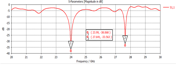
The S-parameter is a way of expressing things in general waveforms rather than voltage and current. It describes the amount of waves reflected or transmitted from/through the device. With a device like antenna, there is not only one parameter but 4 others. The former is also known as the S11 reflection factor. In practice, the most common parameter for antennas is S11. S11 represents the amount of power reflected from the antenna, so known as the reflection coefficient (sometimes written as gamma: or return loss) If S11=0 dBm, all power is transmitted to the antenna. It is also reflected from this and since the parameter s is proportional to the electrical power (in truth, the square root of the electrical power).
Figure 3
|
Figure 3 S Parameter |
Figure 4
|
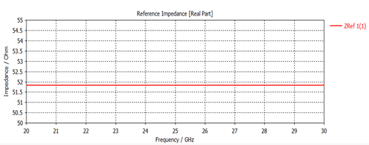
Figure 4 Reference Impedance |
Figure 5
|
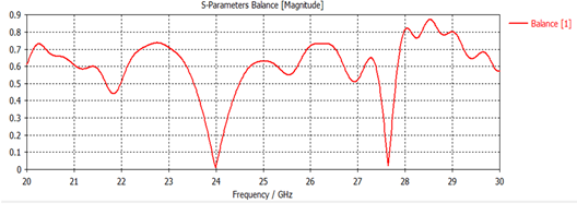
Figure 5 S Parameter Balance |
Figure 6
|
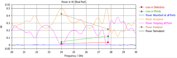
Figure 6 Power in W |
Figure 7
|
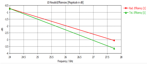
Figure 7 Radiation and Total Efficiency |
Figure 8
|
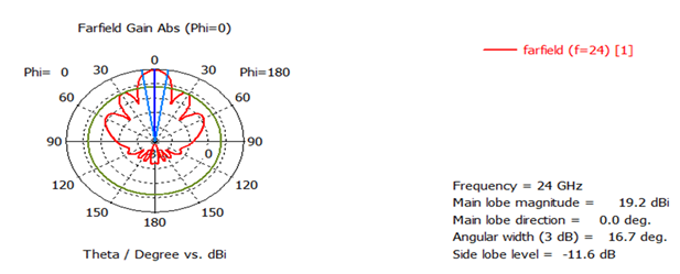
Figure 8 Far Field, oneband |
Figure 9

|
Figure 9 Far Field, other band |
9. CONCLUSION
The results presented in this work are promising for designing compact antennas, allowing size reduction without sacrificing antenna bandwidth, making antennas useful for many applications conclude that bandwidth, gain, return loss using fractal geometry, slot penetration techniques of various performance parameters Desired values can be achieved Some suggestions for future improvements are given such as improving geometry of fractal structure to get better results Further investigate different techniques, such as using parasitic patch reflective layer, air substrate instead of conventional substrate etc., to achieve microstrip antenna performance parameters can provide great benefits CST simulation results show that antennas It can detect wideband characteristics with a return loss of -38.068 dB at 23.99 GHz and -33.563 dB at 27.641 GHz.
CONFLICT OF INTERESTS
None.
ACKNOWLEDGMENTS
None.
REFERENCES
Banu, A., Yang, B., Xie, J., Yu,
B., Kumar, D., Geran, F., Amiri,
Sh., IEEE, Fontgalland, G., Melo, M. A. B., Valle, R.
R. M. S., Barbin, E., Gao, X.-J., Tseng, L. C., Tarar, M. A., Tahir, F. A., Ullah,
S., Bhatti, F. A., Pachiyaannan, M., . . . Ebazadeh, Y. (2018). Eighteen-pole superconducting CQ filter for future wireless
applications. In IEEE (Vol. 153, pp. 205–211).
Ebazadeh, Y., Ebrahimi, S. M., & Aghdam, A. M. (2018). Metamaterial-based low-profile broadband hexagonal-grid-slotted patch antenna. 2017 International Applied Computational Electromagnetics Society Symposium (ACES) (pp. 1-2). IEEE.
Fontgalland, G., Melo, M.A.B., Valle, R.R.M.S., & Barbin, E. (2013). Metamaterial-inspired wire
antennas. IEEE Transactions on Magnetics,
49(5), 1893-1896.
Gao, S.-C., Li, J., Zhou, M., &
Deng, K. (2019). Dual band circularly
polarized microstrip antenna for ku/ka band satellite
communication arrays. In IEEE Antenna
and Wireless Propagation (Vol. 14, pp. 1831-1833).
Gao, X.-J. et al. (2016). Electromagnetic coupling
reduction in high-profile monopole antennas using single-negative magnetic metamaterials for MIMO applications. IEEE Transactions on Antennas and Propagation, 58, 2894-2902.
Geran, F., & Amiri, S. (2022). Omni-Directional/Multi-Resonance
Monopole Antenna for Microwave
Imaging Systems. 20th Telecommunications
forum TELFOR, 978-1-4673-2984. IEEE.
Goswami, S., Jha, A. K., & Singh, A. (2016). Design, simulation, and fabrication of an ultra-wideband monopole antenna for use in circular cylindrical microwave imaging systems. Australian Journal of Basic and Applied Sciences, 7(2), 674-680.
Jha, N. et al. (2016). Design of rectangular microstrip
patch antenna using particle swarm optimization. International Journal of Advanced Research in Computer and Communication Engineering, 2(7).
Kasinathan, A. (2017). Design and analysis
of rectangular microstrip
patch antenna for GSM application. IJISET -
International Journal of Innovative Science, Engineering & Technology, 1(2).
Khidre, A., Singh Sappal, A., Banu, A., Yang, B.,
Yu, B., Kumar, D., Geran, F., Amiri,
Sh., Fontgalland, G., Melo, M. A. B., Valle, R. R. M.
S., Barbin, E., Gao, X.-J., Tseng, L. C., Tarar, M. A., Tahir, F. A., Ullah,
S., Bhatti, F. A., Pachiyaannan, M., . . . Ebazadeh, Y. (2016). Wide Band
Dual-Beam U-Slot Microstrip antenna.
IEEE Transactions on Antennas and Propagation, 61(3),
1415–1418.
Kumar, D. et al. (2019). Enhancement of the gain for microstrip antennas using negative permeability metamaterial on LowTemperature Co-Fired Ceramic (LTCC) substrate. IEEE Antennas Wireless Propagation Letters,
12, 429-432.
Liu, W., Li, Z., & Yin, X.
(2015). A compact L-slot microstrip
antenna for quad band applications in wireless communication. Global Journal of Researches in Engineering (F), 12(2).
Oujarroudi, N. et al. (2017). Dual band microstrip patch antenna array for next generation wireless sensor network applications. Electronic and Power Engineering Department, 39-43.
Pachiyaannan, M. (2017). E-shape
microstrip patch antenna
design for wireless applications. International
Journal of Innovative Science, Engineering & Technology,
1(3).
Sappal, A. S., Banu, A., Yang, B., Xie, J., Yu, B., Kumar, D., Geran, F., Amiri, Sh., Fontgalland, G., Melo, M. A. B., Valle, R. R. M. S.,
Barbin, E., Gao, X.-J., Tseng, L. C., Tarar, M. A., Tahir, F. A., Ullah,
S., Bhatti, F. A., Pachiyaannan, M., . . . Ebazadeh, Y. (2018). Design of Microstrip slot Antenna foe WiMAX Apllication.
In IEEE, IEEE International Conference on
Communications and Signal Processing (ICCSP) (pp.
645–649).
Swati, S., Das, S., & Bibhuti, B. (2019). Analysis and design of dual band compact stacked Microstrippatch antenna with defected
ground structure for WLAN/WiMax applications.
International Journal of Electron Commun (AEÜ).
Tarar, M. A., Tahir, F. A., Ullah, S., & Bhatti, F. A. (2013). Compact microstrip patch antenna for ultra-wideband applications. PIERS Proceedings, Stockholm, Sweden.
Tseng, L. C. (2022). Small planar
monopole antenna with a shorted parasitic inverted-L wire for wireless communications in the 2.4, 5.2, and 5.8 GHz bands.
IEEE Transactions on Antennas and Propagation, 52(7),
1903-1905.
Yang, B., & Xie, J. (2019). Compact wideslot tri band antenna for WLAN/WIMAX applications. Progress in Electromagnetics Research Letters, 18–18, 9–18.
Yu, B. (2017). Bandwidth enrichment for micro-strip patch antenna using pendant techniques. International Journal of Engineering Research (IJER), 2(4), 286–289. ISSN: 2319-6890
|
|
 This work is licensed under a: Creative Commons Attribution 4.0 International License
© IJETMR 2014-2024. All Rights Reserved.