
|
|
|
|
BONE NAIL SIZE MEASUREMENT SYSTEM BASED ON MACHINE VISION
Piao Yan 1![]()
![]() ,
Yang Hao 2
,
Yang Hao 2![]()
![]() , Tan Yulong 3
, Tan Yulong 3![]()
![]() ,
Zheng Zehan 2
,
Zheng Zehan 2![]() , Yang Jingcheng 1
, Yang Jingcheng 1![]()
![]()
1 Zhuhai
Huaxing Intelligent Manufacturing Technology Co., Ltd, Zhuhai 519000, China
2 Zhuhai
Huaxing Intelligent Manufacturing Technology Co., Ltd, Zhuhai 519000, China
& School of Mechanical and Electrical Engineering, Guilin University of
Electronic Technology, Guilin 541004, China
3 School
of Mechanical and Electrical Engineering, Guilin University of Electronic
Technology, Guilin 541004, China
|
|
|
ABSTRACT |
|
|
Aiming at the
problems of low measurement efficiency and poor accuracy consistency in the
traditional measurement methods of medical bone nails, a set of bone nail
size measurement system based on machine vision was developed. Firstly, the
edge position of the bone nail was located by setting the ROI area. Then the
Canny algorithm is used to extract the edge accurately, and the edge points
are screened by threshold, and the edge points are fitted into straight line
segments by least square method for size measurement. Finally, using the
Halcon image software platform, the shape matching method was used to match
and locate the bone nails, and the batch detection of bone nails was
realized. The experimental results show that the measurement accuracy of the
system is up to ±0.01mm, the average detection time of a single picture is
54ms, the measurement accuracy is high, the running speed is fast, and it can
meet the demand of industrial real-time detection. |
|||
|
Received 06 December 2024 Accepted 01 January 2024 Published 24 January 2025 Corresponding Author Yang
Jingcheng, qi.yang@hximt.com DOI 10.29121/ijetmr.v12.i1.2025.1523 Funding: This research
received no specific grant from any funding agency in the public, commercial,
or not-for-profit sectors. Copyright: © 2025 The
Author(s). This work is licensed under a Creative Commons
Attribution 4.0 International License. With the
license CC-BY, authors retain the copyright, allowing anyone to download,
reuse, re-print, modify, distribute, and/or copy their contribution. The work
must be properly attributed to its author.
|
|||
|
Keywords: Machine Vision,
Line Detection, Halcon, Shape Matching |
|||


1. INTRODUCTION
The quality inspection technology requirements of enterprises are gradually improving in tandem with the rapid advancement of contemporary industrial production automation. The primary method of traditional manual measurement is contact measurement, which involves the use of vernier calipers, micrometers, three coordinates, and other measuring instruments. While these methods have a high level of accuracy and a consistent measurement effect, they are not particularly efficient. The introduction of machine vision measurement can achieve non-contact high-precision measurement, which can quickly, accurately, and precisely measure products in large-volume industrial automated production. This capability meets the demands of modern enterprises for high-efficiency and high-precision manufacturing, and contributes to the upgrading and transformation of enterprises [Song Shuaishuai et al. (2021)-Zheng et al. (2021)].
In 2013, the Chen Zhang team from Nanjing University of Aeronautics and Astronautics proposed an innovative vision-based milling cutter endface wear measurement method Zhang & Zhang (2013). This method effectively enhances the detection accuracy by acquiring tool wear information through machine vision technology and establishing an accurate detection algorithm for wear edge points with sub-pixel accuracy. The Ren Yongqiang team from Hefei University of Technology proposed a machine vision-based technology for measuring the size of the inner and outer diameters of diesel engine cylinder lines in 2020 REN Yong-qiang et al. (2020). This technology utilizes bilateral filtering, morphological gradient algorithms for image preprocessing, edge detection, and bilinear interpolation algorithms to achieve high-precision measurements of the cylinder liner. Subsequent research in comparable disciplines was established on the basis of these findings. Zhao Qiwei, Li Yongqiao, and others proposed a machine vision method for measuring the bore set's geometric parameters in the same year ZHAO Qi-wei et al. (2020). This method substantially enhanced the measurement efficiency and accuracy. Jiang Zhansi Zheng Hongxin et al. (2024)-Chen Xiaoxin et al. (2024)] et al. proposed some deep learning methods and applied them in surface defect detector of dental Nails.
Inspired by these studies, this paper develops a machine vision-based bone nail dimensional measurement system for bone nails, a metal product used to treat skeletal trauma. Aiming at the discontinuity problem of straight line segments at the edge of bone nails, the system improves the straight line extraction method on the basis of Canny algorithm, and adopts the shape matching technology to realize the high-efficiency and high-precision detection of bone nails, effectively solving the problem of small inner and outer diameters of bone nails, complex shape, and high difficulty in measurement HE Wei et al. (2018), which improves the measurement efficiency and meets the clinical needs.
2. MATERIALS AND METHODS
2.1. Components of Hardware and Software Structures in Machine Vision Inspection
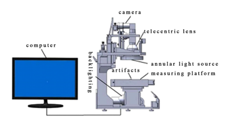
The visual measurement system is depicted in Figure 2, which is composed of an industrial camera, light source, double telecentric lens, computer, and motion measurement platform. The visual measurement system firstly obtains the image of the bone nail through the industrial camera combined with the double telecentric optical lens, and then transmits the data to the computer through USB 3.0 and processes the data through the image processing software to detect the outer and inner diameters of the threads of the bone nail in real time.
The system software is developed based on the QT platform and the Halcon library.
Figure 1

|
Figure 1 Bone Nail |
Figure 2
|
Figure
2 Components of
Hardware in the Vision System |
2.2. Acquisition of images
The measurement system uses MV-CA050-11UM vision camera to obtain bone nail pictures. The resolution of the camera is 2448*2048, and the cell size is 3.45 um. In order to minimize the perspective distortion and the condition of near big and far tiny created by the imaging of ordinary lenses, double telecentric lenses are utilized to obtain parallel projection maps. Due to the small size of the bone nails to be measured, the telecentric lens used has a large magnification and a small depth of field, so the design of the tooling fixture as shown in Figure 3makes the imaging of the bone nails clear and obvious contours. When acquiring images, the SDK development kit of the camera is called using QT to trigger the camera to acquire image data, and eventually the image data is input into the computer through USB 3.0. The acquisition effect is shown in Figure 4.
Figure 3

|
Figure 3 Tooling Fixture for Bone Nails |
Figure 4

|
Figure 4 Image of Bone Nails |
3. RESULTS AND DISCUSSIONS
3.1. Line detection and distance measurement
3.1.1. Line detection
1) Setting
of the ROI area
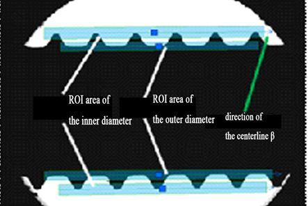
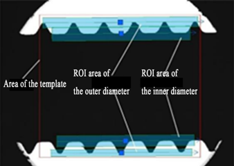
According to the bone nail measurement requirements, the ROI region is set for the inner and outer diameter regions of the bone nail, and the centerline direction β is set to be consistent with the direction to be detected for use in the subsequent straight line fitting algorithm. The extraction area is shown in Figure 5.
Figure 5
|
Figure 5 Inner and Outer Diameter ROI Areas |
2) Edge
detection
The telecentric lens and telecentric parallel light source under the action of the image collected by the edge of the clear contour are evident. To guarantee that the detected edges correspond to the original edges, the Canny [YU Bo et al. (2022)-Zhang & Mu (2020)] algorithm is employed directly to extract the gradient map of the image and the gradient direction map. The algorithm steps are as follows:
·
Gaussian filter
The image is smoothed and denoised using a two-dimensional Gaussian function and the Gaussian formula is as follows:
![]() (1)
(1)
In Eq. (1): σ is the standard deviation.
The original image f(x,y) is convolved with the Gaussian function of Eq. (1), resulting in the following equation:
![]() (2)
(2)
In Eq. (2): f_s (x,y) is the smoothed image.
·
Calculate the image gradient
The gradient image g(x,y) and the gradient direction map θ(x,y) are obtained by convolving the smoothed image using a first order difference H(x,y) template as shown in Eq. (3):
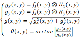 (3)
(3)
In Eq. (3): g_x (x,y) is the X-direction gradient, g_y (x,y) is the Y-direction gradient.
· Non-maximum suppression
Refinement of edges by non-maximum suppression of the gradient image. Take a point of the region in the gradient image as the center point O(x,y), define four directions d_k: -45°, 0°, 45°, 90°, find the direction d_k closest to θ(x,y), compare the gradient value of O(x,y) ith the two pixels adjacent along the d_k direction, if O(x,y) is the largest, it is retained, otherwise it is set to zero.
· Dual threshold processing
Setting high threshold T_H and low threshold T_L to process the image after non-extremely large value suppression, the strong edge image is obtained by eliminating the pseudo edges through high thresholding, and the low thresholding fills in the seam-connected edges in the strong edge image through 8-connection method.
The outer diameter gradient map and gradient direction map obtained by the above stages are shown in Figure 6(a)(b), and the inner diameter gradient map and gradient direction map are shown in Figure 7(a)(b).
Figure 6


|
Figure 6 Outer Diameter Edge
Detection Diagram (a) Gradient Diagram of the Outer Diameter (b) Outer Diameter Gradient
Direction Diagram |
Figure 7


|
Figure 7 Inner Diameter Edge
Detection Diagram (a) Gradient
Diagram of the Inner Diameter (b)
Inner Diameter Gradient Direction Diagram |
3) Linear
fitting
When measuring the inner and outer diameters of the bone
nails, since the measured edge straight line segments are non-continuous, they
cannot be detected using traditional straight line detection methods such as
the Hough transform CAO Hao-peng et al.(2018), the edge points
detected in step 2) are screened by the centreline direction β set in step
1), firstly, a gradient threshold ε is set, the gradient map ![]() is
traversed, and the
is
traversed, and the ![]() is screened for the pixel
points, and then set the gradient direction threshold λ to judge the
gradient direction
is screened for the pixel
points, and then set the gradient direction threshold λ to judge the
gradient direction ![]() of
the pixel points, if it belongs to it, the pixel point (x,y) is added into the
container V, otherwise, continue filtering. Finally, the points screened in
container V are fitted as straight line segments by the least squares method Nie Peng et al. (2022), which can accurately
extract straight lines. Assuming that the screened points are p_1=
of
the pixel points, if it belongs to it, the pixel point (x,y) is added into the
container V, otherwise, continue filtering. Finally, the points screened in
container V are fitted as straight line segments by the least squares method Nie Peng et al. (2022), which can accurately
extract straight lines. Assuming that the screened points are p_1=![]() …
…![]() ,
and straight line segment is y=ax+b, an expression for the parameters a,b can
be obtained:
,
and straight line segment is y=ax+b, an expression for the parameters a,b can
be obtained:
![]() (4)
(4)
![]() (5)
(5)
The specific algorithm flowchart is shown in Figure 8
Figure 8

|
Figure 8 Flowchart of Linear Fitting Algorithm |
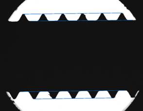
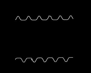
The result of fitting the straight line is shown in Figure 9.
Figure 9
|
Figure 9 Image of Linear Fitting Effect |
3.1.2. Measurement of distance
In this paper, we adopt the standard parts method to calibrate the camera using a standard checkerboard grid to calculate the physical size corresponding to each pixel. The dimensions of the checkerboard grid are standardized, and the distance of each grid is 1 mm. Then take 10 grids in the checkerboard grid and the pixel per unit K can be determined by calculating the ratio between the pixel distance w of the 10 grids in the image and their actual size q Jiao Bo et al. (2022). This can be expressed by the formula: K=q/w.
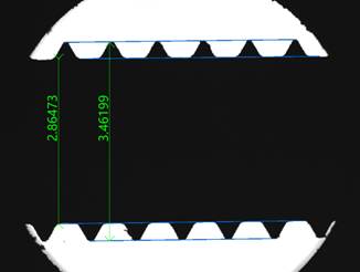
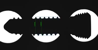
The inner and outer diameters' distances are calculated using the straight line segments that were taken out in chapter 3.1.1. Take the inner diameter as an example, because the two straight line segments extracted are not strictly parallel, so first fix a line segment, extract three points at the four equal parts of another line segment, calculate the distance from each point to the fixed line segment and take the average value. The average value is used as the size of the inner diameter distance. According to the internal and external diameter tolerance requirements, the design interface is shown in Figure 10, the user inputs the design value and the upper and lower limits of the measurement results, if the measurement results are qualified, it will display green, otherwise it will display red, the measurement results are shown in Figure 11.
Figure 10

|
Figure 10 Tolerance Setting Interface |
Figure 11
|
Figure 11 Image of Measurement Effect |
3.2. Bone nail template shape matching
To realize the batch measurement of bone nails, the thread contour line on the bone nails was extracted as a template. Using the correspondence between the template and the ROI region, the new picture samples are matched and localized using the shape matching method LI Yong-jing et al. (2017). Obtain the transformation matrix, apply the transformation matrix with affine transformation to locate the ROI region on the new samples, apply the straight line detection and measurement algorithm on the ROI region, and finally derive the measurement results.
3.2.1. Extraction of the template
Bone nail nut and tail region due to more processing procedures resulting in a more complex shape, while the threaded region of the bone nail production consistency is better, the contour is clear and obvious, so the establishment of the thread matching template and ROI region, through the Canny algorithm to obtain a clear template area edges as shown in Figure 12 and establish a template for matching, the operator for create_shape_model
Figure 12
|
a) Extract
Template Area (b) Extract
The Edges of The Template Area Figure 12 Template Creation and Edge Extraction |
3.2.2. Matching and measurement
In order to precisely determine the location of the ROI region, the bone nail is placed at a different angle and position each time. The transformation matrix is then obtained by matching the shapes of the measured image and the template that was extracted in chapter 3.2.1. The measured image is then subjected to the affine transformation Yang Guihua et al. (2021) to determine the new ROI region and carry out the straight line detection and measurement on it.
Assuming that the center point of the bone nail thread
template is ![]() ,
the measurement target center point
,
the measurement target center point ![]() is obtained by shape matching, and the
matching formula is:
is obtained by shape matching, and the
matching formula is:
 (6)
(6)
In Eq. (6): ∆x is the translation in the X-direction, ∆y is the translation in the Y-direction, and θ is the rotation angle.
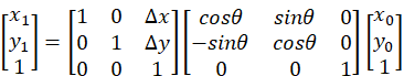
Homogeneous Transformation Matrix HomMat2D is
![]() (7)
(7)
In Eq. (7): R is a 2×2 rotation matrix; t is a
two-dimensional translation vector; ![]() .
.
The ROI region is detected on the new image by the Homogeneous Transformation Matrix HomMat2D, on which the straight line detection and measurement algorithm is applied, and the results are shown in Figure 13.
(a) Measurements of The Bone Nail in The Horizontal State

(b) Measurements of The Bone Nail in The Tilted State
|
Figure 13 Measurement Results of Template Matching |
3.3. Output of results
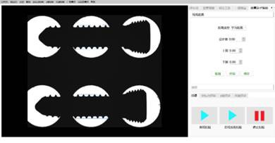
In this paper, the software is jointly programmed by Halcon and QT, and the design of the upper computer interface for bone nail detection is shown in Figure 14. In order to verify the stability and accuracy of the detection system, the inner diameter size of the bone nails was selected for dynamic repeatability measurement to check the stability of the algorithms (Dynamic Repeatability Test is a repetitive measurement of the same product at different positions).
Figure 14
|
Figure 14 Measurement Interface |
As shown in Table 1, a total of 8 groups of internal diameter data were measured, the design value of the internal diameter is 〖2.9〗_(-0.1)^(-0.03) mm, the average value of the dynamic repeatability measurement is 2.8592mm, and the difference between the maximum measurement value and the minimum measurement value is 0.0034mm, so the measurement repeatability precision of the system in this paper is 0.01mm, and the fluctuation of the repeatability of the measurement results is smooth, and the fluctuation of the measurement results is smooth, and the algorithm is robust, and the system is stable. fluctuation of the results is relatively smooth, the robustness of the algorithm is relatively strong, and the system is relatively stable.
Table 1
|
Table 1 Data for Inner Diameter Repeatability Measurements |
||
|
Object of measurement |
The number of
measurements |
Values for dynamic
repeatability measurements (mm) |
|
Inner diameter of bone
nail |
1 |
2.8584 |
|
|
2 |
2.8590 |
|
|
3 |
2.8574 |
|
|
4 |
2.8598 |
|
|
5 |
2.8589 |
|
|
6 |
2.8598 |
|
|
7 |
2.8598 |
|
|
8 |
2.8608 |
|
|
Average value |
2.8592 |
|
|
Difference between
maximum and minimum |
0.0034 |
The internal and external diameter measurements of 15 bone nail workpieces by optical measuring instruments are used as reference values, and the system of this paper is utilized to measure 15 workpieces, and the measurement results are shown in Table 2, from which it can be seen that the measurement accuracy of the system is ±0.01mm, and the detection time of a single picture is 54ms , and the results show that the inspection system of bone nails in this paper can be used for practical industrial inspection.
Table 2
|
Table 2 Measurement Data of Inner and Outer Diameter Sizes of Bone Nails |
||||||
|
Product ID |
Measuring device (mm) |
Algorithms (mm) |
Relative error (mm) |
|||
|
Inner diameter |
Outer diameter |
Inner diameter |
Outer diameter |
Inner diameter |
Outer diameter |
|
|
1 |
2.8625 |
3.4521 |
2.8612 |
3.4672 |
0.0013 |
-0.0151 |
|
2 |
2.8566 |
3.4482 |
2.8627 |
3.4681 |
-0.0061 |
-0.0199 |
|
3 |
2.8572 |
3.4485 |
2.8667 |
3.4640 |
-0.0095 |
-0.0155 |
|
4 |
2.8617 |
3.4529 |
2.8634 |
3.475 |
-0.0017 |
-0.0221 |
|
5 |
2.8562 |
3.4482 |
2.8612 |
3.4601 |
-0.005 |
-0.0119 |
|
6 |
2.8527 |
3.4505 |
2.8610 |
3.4675 |
-0.0083 |
-0.017 |
|
7 |
2.8534 |
3.4497 |
2.8607 |
3.4644 |
-0.0073 |
-0.0147 |
|
8 |
2.8530 |
3.4496 |
2.8658 |
3.4624 |
-0.0128 |
-0.0128 |
|
9 |
2.8584 |
3.4490 |
2.8637 |
3.4633 |
-0.0053 |
-0.0143 |
|
10 |
2.8586 |
3.4531 |
2.8691 |
3.4704 |
-0.0105 |
-0.0173 |
|
11 |
2.8621 |
3.4545 |
2.8670 |
3.4655 |
-0.0049 |
-0.011 |
|
12 |
2.8620 |
3.4485 |
2.8676 |
3.4652 |
-0.0056 |
-0.0167 |
|
13 |
2.8576 |
3.4411 |
2.8636 |
3.4592 |
-0.006 |
-0.0181 |
|
14 |
2.8523 |
3.4428 |
2.8577 |
3.4677 |
-0.0054 |
-0.0249 |
|
15 |
2.8581 |
3.4461 |
2.8648 |
3.4624 |
-0.0067 |
-0.0163 |
|
Average value |
2.8574 |
3.4489 |
2.8637 |
3.4654 |
-0.0062 |
-0.0165 |
|
Detection time |
800ms |
54ms |
----- |
|||
4. CONCLUSIONS
In this paper, a bone nail size measurement system based on machine vision is designed. Combined with the double telecentric optical lens to capture images, the straight line extraction method was improved. The shape matching method is used to locate the detection area of the bone nail and the measurement algorithm is employed to carry out the measurement. The measurement results are compared and analyzed with the optical measuring instruments, and the experiment demonstrates that the measurement accuracy of this system can reach ±0.01mm, and the detection time of a single image is 54ms, which can meet the actual industrial inspection requirements.
CONFLICT OF INTERESTS
None.
ACKNOWLEDGMENTS
This work was supported in part by the Tertiary Education Scientific research project of Guangzhou Municipal Education Bureau under Grant 2024312466 and 2024312474, in part by the Special projects in universities' key fields of Guangdong Province under Grant 2024ZDZX3037, and Innovation Project of Guangxi Graduate Education under Grant YCBZ2024167.
REFERENCES
CAO Hao-peng, ZENG Wei-ming, & SHI Yu-hu (2018). Power Line Detection Based on Hough Transform and Total Least Squares Method [J]. Computer Technology and Development,28(10):164-167.
Chen Xiaoxin, Jiang Zhansi, Piao Yan, Yang
Jingcheng, Zheng Hongxin , Yang Hao & Chen Kequan(2024). SF-Yolov8n:
A Novel Ultra Lightweight and High-precision Model for Detecting Surface
Defects of Dental Nails [J]. IEEE Sensors Journal, 24(12): 20103-20113.
https://doi.org/10.1109/JSEN.2024.3392674
HE Wei,FAN Yubo, & LI Xiaoming (2018).
Recent Research Progress of Bioactivity Mechanism and Application of Bone
Repair Materials[J]. Chinese Journal of Reparative and Reconstructive Surgery,
32(09): 1107-1115.
Jiao Bo,Liu Guoning,& Zhao Mengxuan (2022). Flange Size Measurement Method Based on Machine Vision with Sub-Pixel Precision [J]. Modern Manufacturing Engineering, (07):121-126.DOI:10.16731/j.cnki.1671-3133.2022.07.019.
LI Yong-jing, ZHU Ping-yu, & SUN Xiao-peng (2017). Shape Defect Detection Algorithm of Stamping Parts Based on Shape Template Matching [J]. Journal of Guangzhou University(Natural Science Edition),16(05):62-66.
Nie Peng, Wang Jiaming, & Guo Yongyi (2022). Research on Countersink Hole Depth Detection Method Based on Machine Vision [J]. Tool Engineering,56(09):134-139.
REN Yong-qiang, TU De-jiang, & HAN Shu (2020). Dimension Measurement of Diesel Cylinder Liner Based on Machine Vision [J]. Modular Machine Tool & Automatic Manufacturing Technique,(09):151-153.
Song Shuaishuai,Huang Feng, &
Jiang Yanbin (2021). Analysis on the Research
progress of Geometric Measurement Technology Based on Machine Vision[J].
Electronic Measurement Technology, (03): 22-26.
YU Bo, WU Jing, & ZHOU Qi-bin (2022). An Edge Detection Algorithm Based on Improved Canny Operator [J]. Manufacturing Automation, 44(08):24-26+43.
Yang Guihua, Tang Weiwei, & Lu
Pengpeng (2021). Chip Pin Measurement and Defect
Detection System Based on Machine Vision [J]. Electronic Measurement
Technology,44(18):136-142.DOI:10.19651/j.cnki.emt.2107535.
ZHAO Qi-wei,LI Yong-qiao, & XIE Song-le (2020). Research on Visual Measurement Methodfor Geometric Parameters of Hole Group in Riveted Thin Plate [J]. Machinery Design & Manufacture,(09):158-161.
Zhang C, & Zhang J.(2013).On-line
tool wear Measurement for Ball-End Milling Cutter Based on Machine
vision[J].Computers in Industry,64 (6): 708-719.
https://doi.org/10.1016/j.compind.2013.03.010
Zhang Congcong, & Mu Li (2020). Research on Image Edge Detection Algorithm Based on Machine Vision [J]. Foreign Electronic Measurement Technology,39(12):80-85.DOI:10.19652/j.cnki.femt.2002269.
Zheng Hongxin, Chen Xiaoxin, Cheng Hao, Du
Yixian, & Jiang Zhansi (2024). MD-YOLO: Surface Defect Detector for
Industrial Complex Environments [J]. Optics and Lasers in Engineering (178)
:108170. https://doi.org/10.1016/j.optlaseng.2024.108170
Zheng Ruxin,Sun Qingyun, & Xiao guodong (2021). Research on Workpiece Dimension Measurement Based on Machine Vision [J]. Electronic Measurement Technology,44(16): 110-115.DOI:10.19651/j.cnki.emt.2107065.
|
|
 This work is licensed under a: Creative Commons Attribution 4.0 International License
© IJETMR 2014-2025. All Rights Reserved.