
|
|
|
|
Micropolar fluid flows relative to a swarm of spherical porous shells
Dr. Curtis Boodoo 1![]()
1 Utilities
and Sustainable Engineering, The University of Trinidad and Tobago, Trinidad
and Tobago
|
|
|
ABSTRACT |
|
|
This article investigates the creeping axisymmetric flow of an incompressible micropolar fluid past a swarm of porous shells. Employing the Darcy and a transition Brinkman porous layer, the study presents an analytical model that captures the flow behavior by integrating continuity conditions for velocity, normal and tangential stresses, and microrotations at fluid-porous interface regions. Distinct unit cell techniques, including those proposed by Happel, Kuwabara, Kvashnin, and Mehta and Morse, are analyzed to observe the effects of hydraulic resistivity, porous layer thickness, and porosity on the dimensionless drag for a bounded micropolar fluid system. The results, graphically represented in a series of plots, reveal a complex interplay between these parameters, significantly impacting drag forces and providing insight into the hydrodynamics of a swarm of porous particles, akin to that encountered in oral drug delivery systems. The study
identifies a general inverse relationship between hydraulic resistivity and
drag and highlights the nuanced effects of porous layer thickness and
porosity on fluid resistance, with stark contrasts observed among different
unit cell models. These findings underscore the importance of the chosen unit
cell technique in predicting and optimizing the flow behavior in micropolar
fluid systems. |
|||
|
Received 20 March 2024 Accepted 23 April 2024 Published 07 May 2024 Corresponding Author Dr Curtis
Boodoo, curtis_boodoo@hotmail.com
DOI 10.29121/ijetmr.v11.i5.2024.1426 Funding: This research
received no specific grant from any funding agency in the public, commercial,
or not-for-profit sectors. Copyright: © 2024 The
Author(s). This work is licensed under a Creative Commons
Attribution 4.0 International License. With the
license CC-BY, authors retain the copyright, allowing anyone to download,
reuse, re-print, modify, distribute, and/or copy their contribution. The work
must be properly attributed to its author.
|
|||
|
Keywords: Micropolar
Fluid, Swarm of Porous Shells, Drug Delivery, Unit Cell Technique, Drag
Coefficient, Creeping Flow |
|||


1. INTRODUCTION
Micropolar fluid flow has various applications in different fields. It is used in heat exchangers, cooling nuclear reactors, designing energy systems, and the casting and injection processes of fluids Kocic et al. (2023). Micropolar fluids are also relevant in the flow of human or animal blood, the extraction of crude oil, and the flow of polymer fluids or liquid crystals Kocic et al. (2023). They are utilized in biomedical applications, such as biological, physical, and chemical processes, as well as lubrication systems and hydrodynamic-fluid problems Kethireddy et al. (2022). Micropolar fluids are also important in convective heat and mass transfer, polymer production, and the cooling of particles for metallic sheets Awan et al. (2022). Additionally, micropolar fluids containing small conductive particles have potential applications in drug delivery and localized heating Narla et al. (2022). This paper focuses on the application of micropolar fluid and porous spheres in drug delivery.
The analytical investigation of micropolar fluid flow past a porous sphere has been carried out in several papers. El-Sapa analyzes the axisymmetric creeping flow of micropolar fluid past a porous surface saturated with micropolar fluid using an analytical method El-Sapa (2022). Maurya and Deo study the flow of micropolar fluid through a porous cylinder enclosing a solid cylindrical core under an externally applied magnetic field Khanukaeva (2022). Aparna et al. consider the uniform flow of a viscous fluid past a spherical ball filled with porous medium saturated by micropolar fluid and observe the effects of porosity and micropolarity parameters on the flow and drag Maurya & Deo (2022). Khanukaeva models the flow of micropolar fluid through a spherical cell consisting of a solid core, porous layer, and liquid envelope using the cell model technique Slattery & Bird (1961). Prasad investigates the low Reynolds number flow of an incompressible micropolar fluid past and through a porous sphere and studies the variation of drag force with the permeability parameter Podilay et al. (2022). Khanukaeva analyzed the micropolar liquid filtration through spherical cell membranes with porous layers using micropolar and Brinkman-type equations, investigating hydrodynamic permeability based on media characteristics Khanukaeva (2022).
For the application of oral drug delivery, a collection or swarm of porous particles is involved. The study that follows is aimed at modeling and exploring the hydrodynamics of this swarm of porous particles. Complications arise when modeling complex geometry comprising an assemblage of particles. The two primary methods for handling boundary value problems involving a collection of particles are: the method of reflections and the unit cell technique.
The concept behind the unit cell technique is that a collection of particles can be divided into a number of identical cells, with one particle occupying each cell Happel & Brenner (1983). The boundary value problem is now reduced to a single particle bounded by a fictitious envelope. The cell model is most applicable for a concentration of periodic particles where the effect of the container wall can be neglected. Various cell shapes can be implemented, but it is more convenient to use a spherical envelope as the fictitious surface of the cell.
The boundary conditions imposed on the surface of the envelope represent the interactions with the other porous particles of the assembly. The thickness of the surrounding fluid layer is adjusted so the ratio of the solid volume to the volume of the liquid envelope represents exactly the solid volume fraction of the porous medium.
An early sphere-in-cell model was proposed by Cunningham (1910). He considered particle sedimentation and postulated that the movement of each spherical particle was allowed only within a concentric mass of fluid boundaries. Mehta and Morse Mehta & Morse (1975) adopted Cunningham's approach by assuming the tangential velocity as a component of the fluid velocity, signifying the homogeneity of the flow on the cell boundary. The importance of the Mehta and Morse boundary conditions is that the average flow variables over a cell volume can be scaled to obtain large scale behavior.
Happel (1958) and Kuwabara (1959) independently presented sphere-in-cell models. The major differences between these two models are in the boundary conditions imposed on the outer envelope surface. The Happel model assumes a uniform velocity condition and no tangential stress at the cell envelope surface. This formulation results in an analytically closed solution that is axisymmetric and can be easily used for heat and mass transfer calculations. The Kuwabara cell model uses zero vorticity condition on the cell surface. The Kuwabara formulation requires a small exchange of mechanical energy with the environment. The mechanical power given by the sphere to the fluid is not all consumed by viscous dissipation in the fluid layer Vasin et al. (2008).
Neale & Nader (1974) considered the spherical cell embedded in an unbounded, continuous, homogeneous, and isotropic permeable medium of the same porosity and permeability as the porous particles that make up the swarm.
They used Brinkmans's equation to model the porous regions. Kvashnin (1980) implemented a tangential component of velocity that reaches a minimum with respect to radial distance on the cell surface. This was done to represent the symmetry of the cell.
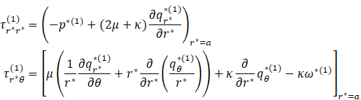
This study investigates the creeping axisymmetric flow of an incompressible micropolar fluid past a porous shell. The porous region is modeled using Darcy equation sandwiched between two transition Brinkman regions. A stream function formulation is used to solve the system. The accompanying boundary conditions used are continuity of velocity, normal and tangential stresses, and non-homogeneous microrotations across the fluid porous region interfaces. At the Brinkman- Darcy interfaces continuity of velocity, normal stresses, microrotations and the Beavers and Joseph condition is implemented. An analytical expression for the dimensionless drag, for the bounded fluid cases as outlined by Happel, Kuwabara, Kvashnin and Mehta, and Morse is derived, and plots of the dimensionless drag as it varies with hydraulic resistivity, porous layer thickness, and porosity are presented.
The study's insights into the hydrodynamics of swarms of porous particles have direct implications for designing more efficient oral drug delivery systems. By understanding the interactions between drug-carrying particles and the surrounding fluid, pharmaceutical engineers can optimize the design of these systems for targeted delivery El-Sapa (2022). The research on micropolar fluid flows through porous shells can be applied to the optimization of heat exchangers, cooling systems for nuclear reactors, and other energy systems. By manipulating parameters such as hydraulic resistivity, porous layer thickness, and porosity, engineers can control fluid resistance and enhance the efficiency of these systems Maurya & Deo (2022).
2. MODEL FORMULATION
The unit cell technique will be used to model a swarm of porous shells in an incompressible micropolar fluid. The porous region is modeled as a transition Brinkman region overlying a Darcy region. The problem geometry is presented in Figure 1.
Figure 1
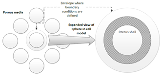
|
Figure
1 Modelling an
Assembly of Porous Spheres Using the Unit Cell Method. |
The boundary conditions implemented in the model for the
single porous shell in a micropolar fluid will be used, with the exception of
the specific boundary conditions at ![]() ,
which is dictated by the particular unit cell technique used.
,
which is dictated by the particular unit cell technique used.
The following unit cell techniques will be implemented at ![]() :
:
1) Happel:
![]() and the tangential stress
and the tangential stress ![]()
2) Kuwabara:
![]() and the vorticity,
and the vorticity, ![]()
3) Kvashnin:
![]() and
and ![]()
4) Mehta
and Morse ![]() and
and ![]()
In the analysis for the single porous shell the radius ![]() was arbitrarily chosen. This will not be the
case for the analysis involving the swarm of porous particles. To ensure the
same ratio of the solid volume to the volume of the liquid envelope represents
exactly the solid volume fraction of the porous medium, the following
expression is utilized:
was arbitrarily chosen. This will not be the
case for the analysis involving the swarm of porous particles. To ensure the
same ratio of the solid volume to the volume of the liquid envelope represents
exactly the solid volume fraction of the porous medium, the following
expression is utilized:
volume fraction of the porous medium ![]() particle volume fraction in the cell
particle volume fraction in the cell
In dimensionless form this is:
![]()
All unit cell techniques utilize the boundary condition ![]() at
at ![]() .
It is the second boundary condition that changes for a specific unit cell
technique.
.
It is the second boundary condition that changes for a specific unit cell
technique.
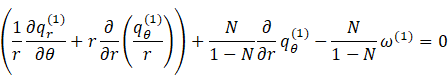
1) Happel:
![]()
the dimensionless tangential stress is given by:
Therefore:
2) Kuwabara:
![]()
3) Kvashnin:
4) Mehta
and Morse:
![]()
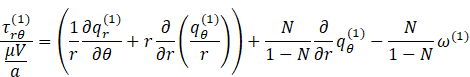
2.1. Dimensionless Drag
An expression for the dimensionless drag on a porous shell in a micropolar fluid was derived and given by Happel & Brenner (1983) as:
![]()
Where for a micropolar fluid [19]
which gives in dimensionless form:
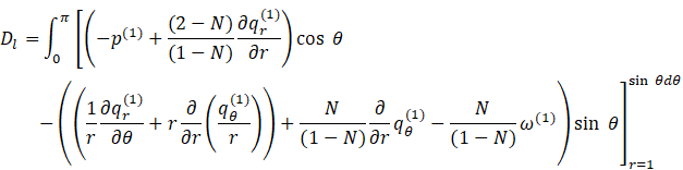
where: ![]() is the dimensionless drag
is the dimensionless drag
The analysis, plots and discussion were all for an unbounded micropolar fluid. In using the various unit cell techniques, boundary conditions are specified on the outer envelope. This represents a bounding of the micropolar fluid.
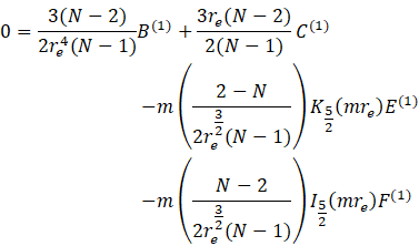
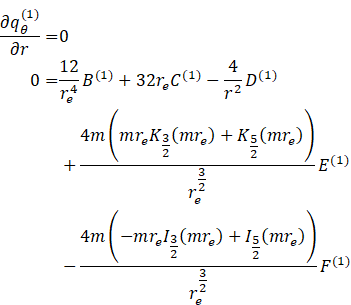
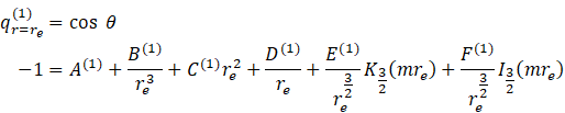
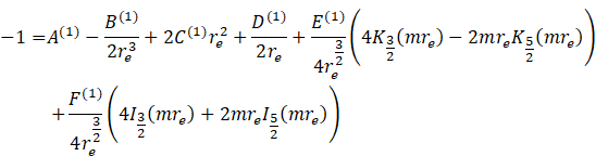
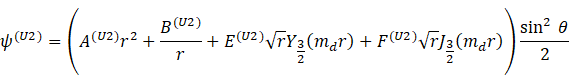
The stream functions for the various regions were solved and given below. The outer micropolar fluid stream function for the unit cell technique is given from as:

The inner micropolar region stream function is given from as:
![]()
and the Brinkman regions as:
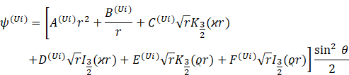
where ![]() or
or ![]()
The Darcy region from is:
where ![]() specifies a unit cell technique: Happel
specifies a unit cell technique: Happel ![]() ,
Kuwabara
,
Kuwabara ![]()
![]() ,
Kvashnin
,
Kvashnin ![]() and Mehta and Morse
and Mehta and Morse ![]() .
.
The constants are solved using the boundary conditions given in the analysis for the single porous shell, which is replaced by boundary condition for Happel, Kuwabarra and Kvashnin unit cell techniques respectively.
The dimensionless drag, ![]() for the unit cell technique is derived as:
for the unit cell technique is derived as:
![]()
3. RESULTS AND DISCUSSIONS
Plots of the
dimensionless drag ![]() for the various unit cell techniques, as they
vary with hydraulic resistivity
for the various unit cell techniques, as they
vary with hydraulic resistivity ![]() , porous layer thickness
, porous layer thickness ![]() and porosity
and porosity ![]() are provided in Figure 1, Figure 2 and Figure 3 respectively. For all three plots the
Mehta and Morse unit cell conditions vary significantly with Happel, Kvashnin
and Kuwabara. In Figure 1 through Figure 3, the presented data clearly delineate
the effects of hydraulic resistivity, porous layer thickness, and porosity on
drag within micropolar fluid flows through various unit cell techniques. Figure 1 illustrates the inverse relationship
between hydraulic resistivity and drag, a trend consistent across all unit cell
models. Figure 2 shows the non-linear effect of porous
layer thickness on drag, with the Mehta and Morse model exhibiting a unique
trend of increased drag with increased thickness, contrary to the other models.
Finally, Figure 3 highlights the critical dependency of
drag on porosity, showing a significant reduction as porosity approaches unity.
are provided in Figure 1, Figure 2 and Figure 3 respectively. For all three plots the
Mehta and Morse unit cell conditions vary significantly with Happel, Kvashnin
and Kuwabara. In Figure 1 through Figure 3, the presented data clearly delineate
the effects of hydraulic resistivity, porous layer thickness, and porosity on
drag within micropolar fluid flows through various unit cell techniques. Figure 1 illustrates the inverse relationship
between hydraulic resistivity and drag, a trend consistent across all unit cell
models. Figure 2 shows the non-linear effect of porous
layer thickness on drag, with the Mehta and Morse model exhibiting a unique
trend of increased drag with increased thickness, contrary to the other models.
Finally, Figure 3 highlights the critical dependency of
drag on porosity, showing a significant reduction as porosity approaches unity.
Figure 2
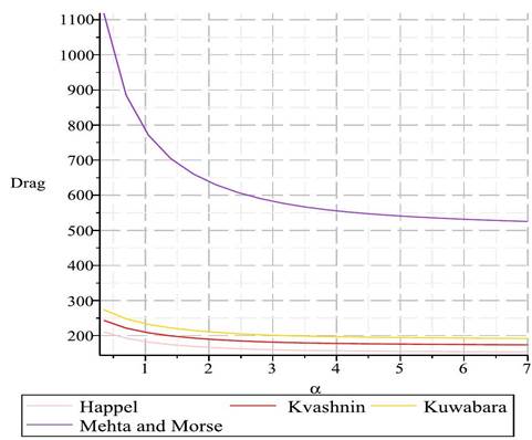
|
Figure 2 Drag Plots for Varying
Hydraulic Resistivity α, using the Different Unit Cell Techniques. |
Figure 3
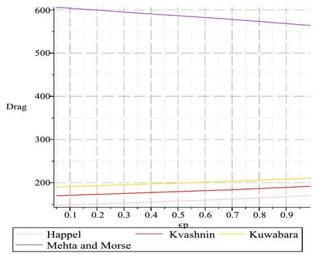
|
Figure
3 Drag Plots for Varying Porous
Layer Thickness ϵ_p, using the Different Unit Cell Techniques. |
Figure 4
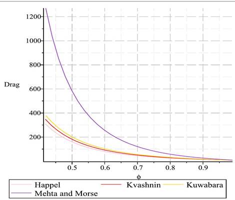
|
Figure 4 Drag Plots
for Varying Porosity ϕ, using the Different Unit Cell Techniques. |
The values of ![]() for the different plots is much higher than
for the different plots is much higher than ![]() , for an unbounded single porous shell in
a micropolar fluid. The porosity,
, for an unbounded single porous shell in
a micropolar fluid. The porosity, ![]() , used in most of the plots, coincides
with
, used in most of the plots, coincides
with ![]() The outer cell envelope where the boundary
conditions are imposed is 0.26 units away from the outer porous surface. To
reproduce the results for an unbounded fluid,
The outer cell envelope where the boundary
conditions are imposed is 0.26 units away from the outer porous surface. To
reproduce the results for an unbounded fluid, ![]() , or
, or ![]() . From observing Figure 3, as
. From observing Figure 3, as ![]() decreases drastically.
decreases drastically.
There is a
decrease in ![]() as
as
![]() , increases (Figure 1). Higher values of
, increases (Figure 1). Higher values of ![]() , coincide with lower values of
permeability
, coincide with lower values of
permeability ![]() . The fluid experiences a greater
resistance to fluid flow within the porous region. A lower volume of fluid
penetrating the porous shell means lower frictional forces experience by the
shell and hence a lower
. The fluid experiences a greater
resistance to fluid flow within the porous region. A lower volume of fluid
penetrating the porous shell means lower frictional forces experience by the
shell and hence a lower ![]() . This behavior was also present in the
single porous shell model.
. This behavior was also present in the
single porous shell model.
As the
thickness of the porous layer ![]() , increases there is an overall decrease
in
, increases there is an overall decrease
in ![]() for the Happel, Kvashnin and Kuwabara unit
cell models. This is opposite for the Mehta and Morse unit cell model where
for the Happel, Kvashnin and Kuwabara unit
cell models. This is opposite for the Mehta and Morse unit cell model where ![]() decrease as
decrease as ![]() increases. The drag
increases. The drag ![]() , for the single porous shell decreases
as
, for the single porous shell decreases
as ![]() is
increased. This behavior matches
is
increased. This behavior matches ![]() with
with ![]() for the Mehta and Morse unit cell model.
for the Mehta and Morse unit cell model.
4. CONCLUSIONS and RECOMMENDATIONS
The analysis of the dimensionless drag ![]() , through the lens of
various unit cell techniques, as presented in Figure 1 to Figure 3, provides a deeper
understanding of fluid dynamics in porous media. The results indicate a
consistent inverse relationship between hydraulic resistivity, α,
and drag across all unit cell models, as demonstrated in Figure 1. This relationship
suggests that an increase in hydraulic resistivity—and consequently a decrease
in permeability—leads to a reduction in drag, due to diminished fluid
penetration and lower frictional forces.
, through the lens of
various unit cell techniques, as presented in Figure 1 to Figure 3, provides a deeper
understanding of fluid dynamics in porous media. The results indicate a
consistent inverse relationship between hydraulic resistivity, α,
and drag across all unit cell models, as demonstrated in Figure 1. This relationship
suggests that an increase in hydraulic resistivity—and consequently a decrease
in permeability—leads to a reduction in drag, due to diminished fluid
penetration and lower frictional forces.
Figure 2 further elaborates on
the effects of porous layer thickness, ![]() , on drag,
showcasing that an increase in thickness typically correlates with a decrease
in drag within the Happel, Kvashnin, and Kuwabara models. Contrastingly, the
Mehta and Morse model exhibits an anomalous increase in drag with increasing
porous layer thickness, suggesting a complex interaction between porous layer
geometry and fluid flow that warrants experimental investigation.
, on drag,
showcasing that an increase in thickness typically correlates with a decrease
in drag within the Happel, Kvashnin, and Kuwabara models. Contrastingly, the
Mehta and Morse model exhibits an anomalous increase in drag with increasing
porous layer thickness, suggesting a complex interaction between porous layer
geometry and fluid flow that warrants experimental investigation.
The dependency of drag on porosity, ϕ, is visually captured
in Figure 3. As porosity approaches
unity, we observe a steep decline in drag, indicating that higher porosity
levels are conducive to reduced fluid resistance. This trend aligns with the
theoretical expectations for unbounded fluids, where higher porosity equates to
lesser obstruction to fluid flow.
The consistent inverse relationship between hydraulic resistivity and
drag, across all unit cell models, as shown in Figure 1, is particularly
relevant for optimizing heat exchanger designs and improving the efficiency of
cooling nuclear reactors. By strategically manipulating hydraulic resistivity,
it may be possible to control fluid flow resistance to achieve desired temperature
regulation more effectively.
Figure 2’s illustration of the
impact of porous layer thickness on drag, especially the unique trend exhibited
by the Mehta and Morse model, has direct implications for the design of energy
systems and the casting and injection processes of fluids. The understanding of
how drag changes with layer thickness can aid in refining these processes to
minimize energy loss and enhance the precision of fluid manipulation.
Moreover, the significant reduction in drag with increasing porosity, as
depicted in Figure 3, underpins the
applications in biological systems, such as blood flow, where the reduction in
drag can potentially lead to less damage to blood cells in artificial devices.
This insight also extends to the extraction of crude oil, where increased
porosity could be beneficial for reducing the energy required for extraction.
In the specific context of drug delivery, where the study focuses, the ability to predict and control the hydrodynamics around porous particles becomes critically important. The cell models and corresponding drag behaviours analysed here can inform the design of drug delivery systems that rely on the micro-scale interactions between the drug-carrying particles and the surrounding fluid. This can lead to more efficient and targeted delivery, potentially improving therapeutic outcomes.
CONFLICT OF INTERESTS
None.
ACKNOWLEDGMENTS
None.
REFERENCES
Awan, A. U., Ahammad, N. A., Ali, B. M., Tag-Eldin, E., Guedriand, K., Gamaoun, F. (2022, Jun.). Significance of Thermal Phenomena and Mechanisms of Heat Transfer through the Dynamics of Second-Grade Micropolar Nanofluids, 14(15). https://doi.org/10.3390/su14159361
Cunningham, E. (1910, Mar.). On the Velocity of Steady Fall of Spherical Particles through Fluid Medium, Proc. R. Soc. Lond. Ser. A, 83(563), 357-365. https://doi.org/10.1098/rspa.1910.0024
El-Sapa, S. (2022, Jun.). Cell Models for Micropolar Fluid Past a Porous Micropolar Fluid Sphere with Stress Jump Condition, 34(8). https://doi.org/10.1063/5.0104279
Happel, J. (1958, Jun.). Viscous Flow in Multiparticle Systems: Slow Motion of Fluids Relative to Beds of Spherical Particles, AIChE J., 4(2), 197-201. https://doi.org/10.1002/aic.690040214
Happel, J., & Brenner, H. (1983). Low Reynolds Number Hydrodynamics: with Special Applications to Particulate Media. Springer. https://doi.org/10.1007/978-94-009-8352-6
Kethireddy, B., Reddyand, G. J., Basha, H. (2022, Jun.). Bejan's Thermal and Mass Flow Visualization in Micropolar Fluid. https://doi.org/10.1080/17455030.2022.2088887
Khanukaeva, D. (2022, Jun.). Filtration of Micropolar Liquid Through a Membrane Composed of Spherical Cells with Porous Layer, 34(3). https://doi.org/10.1007/s00162-020-00527-x
Kocic, M. M., Stamenkovic, Z., Petrovićand, J., Bogdanović-Jovanović, J. (2023, Jun.). MHD Micropolar Fluid Flow in Porous Media, 15(6). https://doi.org/10.1177/16878132231178436
Kocic, M. M., Stamenkovic, Z., Petrovićand, J., Bogdanović-Jovanović, J. (2023, Mar.). Control of MHD Flow and Heat Transfer of a Micropolar Fluid through Porous Media in a Horizontal Channel, 8(3). https://doi.org/10.3390/fluids8030093
Kuwabara, S. (1959, Apr.). The Forces Experienced by Randomly Distributed Parallel Circular Cylinders or Spheres in a Viscous Flow at Small Reynolds Numbers, J. Phys. Soc. Jpn., 14, 527. https://doi.org/10.1143/JPSJ.14.527
Kvashnin, A. G. (1980). Cell Model of Suspension of Spherical Particles, Fluid Dyn., 14(4), 598-602. https://doi.org/10.1007/BF01051266
Maurya, P. K., & Deo, S. (2022, Jun.). MHD Effects on Micropolar Fluid Flow Through a Porous Cylinder Enclosing an Impermeable Core, 13(5). https://doi.org/10.1615/SpecialTopicsRevPorousMedia.2022042199
Mehta, G. D., & Morse, T. F. (1975, Sep.). Flow Through Charged Membranes, J. Chem. Phys., 63(5), 1878-1889. https://doi.org/10.1063/1.431575
Narla, V. K., Tripathiand, D., & Bhandari, D. S. (2022, Jun.). Thermal Analysis of Micropolar Fluid Flow Driven by Electroosmosis and Peristalsis in Microchannel, 43(1). https://doi.org/10.1080/01430750.2022.2091034
Neale, G., & Nader, W. (1974, Aug.). Practical Significance of Brinkman's Extension of Darcy's Law: Coupled Parallel Flows within a Channel and a Bounding Porous Medium, Can. J. Chem. Eng., 52(4), 475-478. https://doi.org/10.1002/cjce.5450520407
Podila, A., Podila, P., Pothannaand, N., & Ramana Murthy, J. V. (2022, Feb.). Uniform Flow of Viscous Fluid Past a Porous Sphere Saturated with Micro Polar Fluid, 13(1). https://doi.org/10.33263/BRIAC131.069
Saad, E. I. (2008). Motion of a Spheroidal Particle in a Micropolar Fluid Contained in a Spherical Envelope, Can. J. Phys., 86(9), 1039-1056. https://doi.org/10.1139/p08-045
Slattery, J. C., & Bird, R. B. (1961, Dec.). Non-Newtonian Flow Past a Sphere, 16. https://doi.org/10.1016/0009-2509(61)80034-1
Vasin, S. I., Filippov, A. N., & Starov, V. M. (2008, Jun.). Hydrodynamic Permeability of Membranes Built up by Particles Covered by Porous Shells: Cell Models. Adv. Colloid Interface Sci., 139(1-2), 83-96. https://doi.org/10.1016/j.cis.2008.01.005
|
|
 This work is licensed under a: Creative Commons Attribution 4.0 International License
© IJETMR 2014-2024. All Rights Reserved.