
|
|
|
|
Ex-Situ-Evaluation of new materials such as copper compounds for zinc-air battery with the aim of getting a secondary zinc-air battery
Vinod-Kumar Banoth 1, Martin Engelke 1, David Fuchs 2,
Thorsten Hickmann 1![]() , Falko Mahlendorf 2
, Falko Mahlendorf 2
1 Eisenhuth
GmbH Co. KG, Osterode, Germany
2 Fakultaet Für Ingenieurwissenschaften, Lehrstuhl für Energietechnik,
Duisburg, Germany
|
|
|
ABSTRACT |
|
|
Zinc airflow
batteries are popular for large-scale energy storage due to their high-volume
density, environmental safety, and economic feasibility of production and
recycling. There is going to be a lot of research in order
to realize a zinc-air battery as a secondary battery. One potential
option in order to overcome this challenge is to use
other anode materials, which are stable in the alkaline medium. The main
objective of this work is to present the most influencing factors for the production of copper compounds with thermoplastic
as binder and graphite as a secondary filler material. In addition, copper
compounds are evaluated based on chemical and electrical tests. |
|||
|
Received 27 January 2024 Accepted 28 February 2024 Published 14 March 2024 Corresponding Author Thorsten
Hickmann, t.hickmann@eisenhuth.de DOI 10.29121/ijetmr.v11.i3.2024.1414 Funding: This research
received no specific grant from any funding agency in the public, commercial,
or not-for-profit sectors. Copyright: © 2024 The
Author(s). This work is licensed under a Creative Commons
Attribution 4.0 International License. With the
license CC-BY, authors retain the copyright, allowing anyone to download,
reuse, re-print, modify, distribute, and/or copy their contribution. The work
must be properly attributed to its author.
|
|||
|
Keywords: Zinc Air
Battery, Material Anode, Electrical Resistance, and Copper Compound |
|||


1. INTRODUCTION
Zinc-air batteries have the potential to function as cost-effective, environmentally friendly, and safe electrochemical energy storage systems in a wide range of industrial applications. The main arguments in favor of developing marketable systems lie in the existing infrastructure for globally established zinc-air primary cells, the high availability and cost-effectiveness of the active material, and the environmental compatibility of the complete system Feldhaus & Vahlenkamp (2010). The greatest challenge in increasing the performance of rechargeable zinc-air power storages lies in avoiding or minimizing the growth of dentritic zinc structures during the use. Zinc dendrites are branched crystal structures that can form on the zinc anode and can lead to short circuits if they break through the electrolyte. This is a major problem for the rechargeability of zinc-air batteries, as it can significantly affect the life and performance of the battery Curà et al. (2023).
The formation of zinc dendrites is influenced by various factors, including current density, charge and discharge rate, temperature, and electrolyte composition. Research is focused on finding ways to minimize or prevent the formation of zinc dendrites in order to develop rechargeable zinc-air batteries that offer longer life and better performance. Some approaches to tackling this problem include material innovation; using new materials for the anode and cathode can also help reduce zinc dendrite formation. Design improvements: The design of the battery can be engineered to make dendrite formation more difficult. By separating layers or using unique electrode structures, this is possible to control Ramin et al. (2020). In zinc airflow batteries, copper compounds play a key role in reducing the weight and cost of the cell, and although this compound is meant for a single-cell testing. The metallic plate at the positive electrode is referred to as the air electrode in this study. In a Zinc-Air battery, the zinc reacts as anode material with oxygen (O2) out at the air electrode. Zinc-air batteries can have a high power density if they are designed as flow reactors with high-performance oxygen electrodes. In addition, zinc particles enriched in alkaline solution are used as the electrolyte. Mahlendorf et al. (2018). The zinc-air discharge efficiency of these flow batteries under the effects of sodium is high. However, the technology is still in its development phase. Nevertheless, the technology is available at various levels for further upgrades, and continuous research needs to be carried out to improve performance, reduce costs, extend the operating time, and extend the operating life.
This paper's work was inspired by the desire to make the zinc-air battery work better by creating a copper bipolar plate that can work as an air electrode plate and last a long time in an electrolyte solution of potassium hydroxide (KOH). The ultimate goal is to develop a new material based on copper as a new type of air electrode with low weight and higher stability in the aqueous medium with no indication of corrosion. As per Hosseini et al. (2018) it is proved that the performance of the zinc-air flow batteries is influenced by the corrosion and passivation of bipolar plates. Therefore, this paper aims to show how the status is when using new materials, such as copper compound to develop a new electrode for a zinc cycle battery. A 1000-hour ageing test in a potassium hydroxide (KOH) water solution was used to see how useful the copper compound might be as an electrode material. There is a steady increase in the resistance of the cell when the copper compound and especially compound with graphite filler are applied in the single-cell zinc-airflow battery test. To optimize the production of the copper plates, it is only possible by the compression molding process using PEEK-based molds (PEEK = polyetheretherketon), since PEEK material can withstand the compression molding at 50°C below its melting temperature of 300–320 °C Howell & Fukumoto (2014).
2. Materials and Methods
This
section is to give an overview of the different materials used for the project
concerning the filler material and different polymers as binders.
2.1. Electrical filler materials
Polymers act as binders for the conductive materials. The proportion of electrically conductive filler in the composite matrix is responsible for the current transport through the bulk of composite. Fillers are based on two types: on the one side these are metallic species, and on the other side are carbon-based derivatives commonly used for composite bipolar plates. Copper and graphite are chosen as primary and secondary fillers.
2.1.1. Copper
The chemical composition of the used copper (purity of > 99.95 %) is shown in Table 1.
Table 1
|
Table 1 Properties
of Used Copper (2023). |
|||
|
species |
Cu |
O |
P |
|
/ wt-% |
> 99.95 |
< 0.0 |
< 0.005 |
2.1.2. Graphite
As a hexagonal crystal system of carbon, graphite is a particularly common species of this element. It has higher electrical and thermal conductivity than both metals and non-metals. The properties of graphite as a filler are presented in Table 2.
|
Table 2 Principal Properties of
Fillers Planes
et al. (2012). |
|
|
Graphite |
|
|
Density / g cm–3 |
2 – 2.25 |
|
Particle size / µm |
50 – 500 |
|
Specific surface area / m2
g–1 |
6.5 – 20 |
|
Aspect ratio / – |
~ 1 |
|
Electrical
conductivity / S cm–1 |
400
– 1250 |
2.2. Polymers
As already mentioned, the electrical fillers determine the conductivity of the composite material Hickmann (2021). The polymers can also influence the electrical conductivity in various ways, such as their surface energy and ability to disperse the filler homogeneously. Thermoplastics or duromers are regarded as suitable binders in industrial applications. For these experiments, thermoplastics used as polymer materials.
2.2.1. Thermoplastics
Various researchers investigated different thermoplastic usages for bipolar plate applications depending on the various temperatures of operations. The most commonly used thermoplastics are polypropylene (PP) and polyvinyliden fluoride (PVDF) for the bipolar plates. The main purpose of using polypropylene (PP) is that it has good mechanical properties, low cost, and easy processing as it melts at low temperatures Tariq et al. (2023). Since, the copper composite bipolar plates are in contact with the potassium hydroxide (KOH) electrolyte in zinc airflow batteries, Polyvinylidene fluoride (PVDF) is one of the polymers that are most suitable for this medium of application with good barrier properties.
Futhermore, it is also sufficiently resistant to acids and alkalis as well as moisture and has the required mechanical properties Dallaev et al. (2022).
2.3. Molding process and Mold material
The most popular production technique for small and intermediate batches of bipolar plate is compression molding Mahlendorf & Jansen (2009). Compression molding is a complex process that and parameters varies with mold material, filler, and binders. Mold temperature, compression force used, cooling time, and cooling temperature parameters must be carefully controlled in order to produce a non-porous compound with uniform filler and binder distribution. Moreover, the aim is to produce copper compounds in large quantities and quality that are equivalent to standard bipolar plates. Two different molds used in this experiment. For the first set of compounds, a steel mold of 1.2314 grade is used, and for the second set of experiments, a PEEK material mold is used.
Table 3
|
Table 3 Mechanical
Properties of Mold Material Rzatki et al. (2015) |
||||
|
Mold material |
Youngs Modulus / GPa |
Poisson coefficent |
Hardness / MPa |
tensile strength / MPa |
|
PEEK |
11 |
0.40 |
90 - 250 |
150 |
|
Steel AISI 304 |
193 |
0.29 |
1265 |
215 |
3. Experimental Set-Up
3.1. Composite Preparation
For copper composite plates, there are different processes for selecting the filler particle size. Before introducing copper or graphite fillers in the compound, these graphite fillers sorted with different particle sizes using sieve analysis. After choosing the required particle size between 150 and 250 µm. Then the graphite powder added with an approximate weight ratio, and the obtained compounds were coded according to the type of filler in the composite, as shown in Table 4. Filler mixed with polymers in the planetary rotating machine at 140 rpm for 35 minutes at 30 °C. The main purpose of adding the graphite filler to copper compound is to increase the conductivity of the compound and to compare the compound durability in the alkaline medium with different filler ratios.
Table 4
|
Table 4 Copper
Compound with Different Ratio for the First Set of Tests. |
|||
|
Compound
type |
Compound
No |
Polymer /
vol-% |
Filler /
vol-% |
|
PVDF + Cu |
M-1 |
70 |
30 |
|
M-2 |
60 |
40 |
|
|
M-3 |
50 |
50 |
|
|
M-4 |
40 |
60 |
|
|
M-5 |
30 |
70 |
|
|
PP + Cu |
M-6 |
70 |
30 |
|
M-7 |
60 |
40 |
|
|
M-8 |
50 |
50 |
|
|
M-9 |
40 |
60 |
|
|
M-10 |
30 |
70 |
|
|
Acryl + Cu |
M-11 |
70 |
30 |
|
M-12 |
60 |
40 |
|
|
M-13 |
50 |
50 |
|
|
M-14 |
40 |
60 |
|
|
M-15 |
30 |
70 |
|
|
PVDF + Cu + Graphite |
M-16 |
22 |
78 [Cu=39
and Graphite=39] |
|
M-17 |
22 |
78
[Cu=19.50 and Graphite =58.50] |
|
|
M-18 |
22 |
78
[Cu=58.5 and Graphite =19.5] |
|
Composites with PP and PVDF based by using the PEEK polymer mold. Compounds out of PEEK mold are complex to produce, as the melting temperature of the PEEK is lower than the steel mold. Moreover, a higher polymer ratio in the compound leads to the flow of the melted composite mix out of the mold during the hot press.
Table 5
|
Table 5Polypropylene and Polyvinylidene Fluoride Based
Compounds for Second Set of Trails |
|||
|
Compound |
PP / vol % |
PVDF / vol-% |
Cu / vol-% |
|
C-6 |
40 |
0 |
60 |
|
C-8 |
20 |
0 |
80 |
|
Z-3 |
0 |
20 |
80 |
4. Characterization
4.1. In-Plane Electrical Conductivity (IPEC)
The conductivity of bipolar plates plays an essential role in the transfer of electrons in addition to providing mechanical strength. Therefore, electrical conductivity characterization is evaluated to understand the various bipolar plate materials’ particle distribution and their arrangement throughout the plate or on the flow fields Taherian (2016). As per Naftaly et al. (2021) measuring voltage drop, the bipolar plate surface resistance can be calculated using Ohm’s. The specific material conductivity is calculated from the surface resistance depending on the sample geometry.
4.2. Scanning Electron Microscopy (SEM)
Bipolar plates must be tested for various quality characteristics. SEM helps to investigate the component surfaces, interfaces, and submicron-scale features of those components, which establish key characteristics influencing the effectiveness of electrochemical energy conversion. To allow for the emergent features required to create a high-quality electrolysis system, each stack should be customized at the micron to sub-micron scale, including a quality bipolar plate. Pitting, crevice, and inter granular corrosion have distinctive visual characteristics under the SEM, making it easy and compatible Yuxi et al. (2020).
4.3. Ageing test of the copper compound
Copper compounds are stored in the 30% KOH electrolyte of a 250-ml solution by maintaining a temperature of 45 °C. The test is performed for 1000 hours, and then the samples are cleaned with iso-propanol. This test was evaluated by weighing the samples before and after the test. Factors that are important to evaluate the composite material during the corrosion test or ageing test are changes in the surface before and after storage, a decrease in material contents, and other residues of KOH from the storage Pilinski et al. (2021). Copper composites are used in the zinc airflow battery, where they counter other chemicals. Therefore, it is important to maintain safety requirements and produce compounds with higher reliability of design and performance.
5. Design of experiments and results
In this study, the investigation of the copper compounds was calculated with varying volumes (%) or weights (%) of polymers, i.e., polypropylene (PP), Polyvinylidene fluoride (PVDF), and acrylic. Due to their higher conductivity, graphite and copper are chosen as the main fillers. For the first set of tests, 18 different compounds are prepared. A maximum of 3500 kN of clamping force is used, and the compounds are demolded at 100 °C. The temperature maintained during the compression molding process varied depending on the polymer used. For PP-based materials, the melting temperature is 65 °C and for PVDF, it is 225 °C. Therefore, for PP, the mold temperature is 185 °C and for PVDF, it is 235 °C. These samples are further investigated for the ageing test. Based on their performance in the ageing test. For the first set, the copper is 95% pure with a particles with 90% particles are of size of 40 µm. However, for the second trial, the copper is 99.9% pure with a particle size of 33 µm. Copper compounds with PVDF are considered a major target for the next set of trials. However, the choice of materials like polypropylene (PP) is based on a comprehensive material and cost analysis that determines the time-related processability of the compound, the electrochemical parameters, and its overall production cost Minke et al. (2016). The mold is cooled to 100 °C and then 300 tons of compression force was applied on the mold. The compound is demolded by cooling the mold at 80 °C.
Therefore, compounds M-1 to M-5 are set as targets to
compare the PP and PVDF based on the second set of trials. The first step is to
choose the polymers and then the filler as per the required weight, and then a
rotatory mixing process performs the mixing of the composite material. During
this mixing process, rubber balls are placed in the material, and then this
material is placed in the closed silicon box, and then it is placed in the
planetary rotating device for 30 minutes at 150 rpm. The thickness of the
compound finalized by the cell design, and the form filled with composite
material. As per experiments carried out at Eisenhuth with PEEK mold, it is
observed that the mold can be deformed after repeated usage at higher
temperatures. Compression molding with the PEEK mold is complex, and the
clamping force should not exceed 2000 KN at 250 °C. After this clamping force,
the PEEK mold is gradually deformed and this is proven Li, and Song Li et al. (2022). For demolding the
compound, Clamping force is gradually increased as the
mold’s temperature increases because the mold cannot resist a higher clamping
force. This case leads to the deformation of the PEEK mold. During the cooling
process, the compound should be cooled in 3 steps of gradual decrement of the
mold temperatures, if not compounds with higher polymers flown out of the mold.
Therefore, cold press begins after the mold cools down to 120 °C.
6. Results and discussions
6.1. In-Plane Electrical Conductivity (IPEC)
Experiments show that there are variations in the conductivity of the compounds among different compression molding parameters. Electrical conductivity is a complex parameter that depends on many independent and dependent factors, like the filler conductivity, homogeneous filler distribution during compression molding, aspect ratio, mixing methods of the material, mechanical process, filler alignment in the compound, and the surface energy of the compound Ye et al. (2004). The first set of test copper and graphite used as filler materials, and the compound with 20 % PVDF without graphite has a conductivity of 660.5 S/cm.
However, a change (5 %) in the polymer or filler material makes a huge difference in the conductivity. As per Forero-Sandoval et al. (2021) when the percentage of fillers increases, their conductivity changes drastically at a given threshold. From Figure 1 we can observe that the compounds with 50 % polymer had 151 S/cm, which is nearly 1 percent of the conductivity, that 10 % polymer-based compound has. Moreover, 10% PVDF based has a conductivity of 15800 S/cm. The difference in the conductivity of the compounds with the steel mold and PEEK is due to the surface of the distribution of the compound. As shown in Figure 1 the conductivity of different compounds concludes that, as the amount of filler material increases, the conductivity of the copper compounds increases.
Figure 1
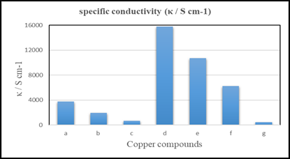
|
Figure
1 Electrical Conductivity of
Different Compound [(a, b and c are Compounds Out of Steel Mold) Varied PVDF;
d, e, f and g Compounds Out of PEEK Mold with Varied
PVDF and PP]. |
6.2. SEM of KOH treated samples for ageing test
Investigations with scanning electron microscopy (SEM) are performed to correlate surface area changes during corrosion or ageing tests performed Maria et al. (2021). Figure 2 shows the SEM images of the three different composite materials that used during the test. For SEM, probe size of the Copper compound obtained was 80µm, and one can observe that there are signs of the deposition of different elements on the surface. This shows a sign of corrosion and an increase in the weight of the samples, and it can be seen that the graphite-base compounds have an uneven surface and few voids. The composition of the elements deposited on the samples can be investigated by using an EDX-analysis (energy-dispersive X-ray) for the next phase of research.
Figure 2
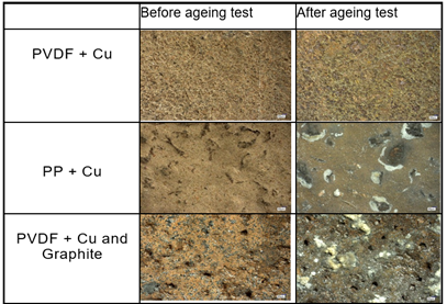
|
Figure
2 SEM Images of Compounds for the
First Set of Trial |
Figure 2 it shows that the compounds with PVDF have a low amount of deposit, while the PP-based compounds have shown signs of deposits. The Polypropylene compounds with and without graphite filler have a mass gain during an ageing test is >1 % but in the PVDF-based compound it is < 0.3 %. Copper compounds for the bipolar plates produced from the PEEK mold are shown in Figure 3. All copper compounds start to oxidize after 10 days when exposed to atmospheric air. After 1000 hours of storing the copper compounds in a 30% KOH solution, these compounds turn light green, causing extensive corrosion. Moreover, this sort of corrosion occurs at a rapid rate when the compounds are dried and exposed to atmospheric air after the ageing test. Moisture conditions are also another important factor to consider when performing the test.
Figure 3
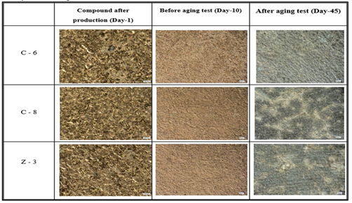
|
Figure
3 Low Magnification SEM Images of
the Surface Morphology of the Copper Compounds Stored in KOH for 1000 hours. |
Figure 3 shows the formation of thin oxide layer formation after 45 days of ageing test in 30 % KOH. Copper compounds produced from the PEEK mold; there is still a formation of an oxide layer that effect further happening of corrosion. The PP-based compounds produced for set-2 experiments have a mass gain of 0.279 % after the ageing test.
6.3. Performance of a zinc cell with a copper compound
The electrochemical cell resistance of a zinc-air laboratory scale system over the test period is shown in Figure 4. The active area has the dimensions of 100 cm² and was developed as part of the "ZinCycle" research project. These copper electrodes are milled and tested in a single-cell test as part of the research project cooperation at the University of Duisburg-Essen. The resistances of the copper connections are evaluated in a flow conductivity measurement setup during the current voltage and cell discharge measurement of the cell.
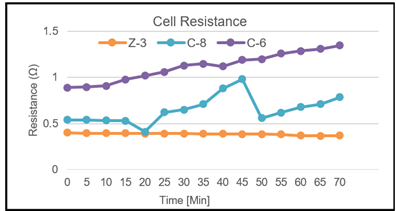
Figure 4
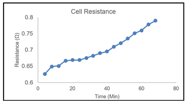
|
Figure
4 Cell Resistance with PVDF Based
Copper Compound Tested in the Zinc Single Cell |
In Figure 4, there is a
continuous increment in the cell resistance after 15 minutes of testing. Similar to Lu
et al. (2022) experiment with the
zinc cell, it is observed that the zinc granules turned black by a sudden drop
of current to a much lower value contributed by hydrogen evolution in the cell.
For the first set of single cell testing, during the 0.8 Ω, the in-cell
hydrogen evaluation remained nearly constant; which
shows that hydrogen evolution occurs either very slowly at this discharge rate,
or not at all. It is likely because the anode potential becomes sufficiently
high to make the hydrogen evolution unfavorable for the cell and this case
shall be investigated in later steps. This affected the copper compound, and
the continuous degradation of copper compounds.
This further affects the zinc slurry in the zinc airflow battery. After 20 minutes of testing, the copper compound begins
to passivate and form an oxidized surface that further increases the resistance
at constant rate.
Figure 5
|
Figure
5 Variations in Cell Resistance of
Different Compounds Produced from PEEK Mold. |
For the second set of tests, three compounds are tested with same parameters and Figure 5 shows the resistance of different compounds produced by the PEEK mold. From the three compounds, Z-3 shows that PVDF-based compounds have a constant resistance, but compounds with PP-based resistance are gradually increasing at a rapid rate.
Figure 6
|
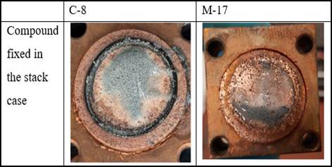
Figure
6 Copper Compound After Single
Cell Test |
Zn slurry can be observed in Figure 6 in the center of the compound. The slurry from the metallic zinc appears shiny prior to initiating the cell discharge. The particles close to the separator and progressively passivated as the cell is discharged further, up to 70 minutes; the cell itself is not entirely passivated. It is interesting to note that the Zn slurry region darkened uniformly across the anode column during discharge. The overall behavior at the beginning of the test was very different and much more interesting than what was observed after 70 minutes, and the resistance increased by more than 50%. Comparing the trend of resistance increment for different compounds, it can be concluded that the PEEK-based set of copper compounds has remained constant for a period, while in the steel-based compound, the resistance is increasing at a rapid rate.
7. Conclusion
Here, the surface variations and the mass change of copper compounds are presented. The conductivity of different compounds and the variations with respect to the mold are studied. This change in mass and conductivity attributed to various factors, like the mixing process of the composite material and the contact of the raw material with other metals. The ageing test of the copper compound from the first batch, immersion of the samples in 250 mL of 30 wt-% KOH showed that the samples with PP-based compounds had a higher material deposition than PVDF-based compounds. The complexity of the production of compounds with higher polymers content are noticed in this process of test. From our experiments, we found that the electrical resistance of the compounds increases with a small increase in polymer content, resulting in a rapid increment in the electrical resistance.
Moreover, our experiments regarding compound production by the PEEK polymer mold showed that there was less gain in mass and the resistance was constant during the single-cell test of the compounds that produced by the PEEK mold. These effects in the formation of the hydrogen at the anode side of the zinc air battery are low when compared to the first set of compounds. Considering the results, the challenge is to decrease the corrosion and evaluation of hydrogen, which we are able to achieve to a certain extent. The presented results are related to the research topics of Eisenhuth GmbH & Co. KG. It is not always possible to meet the goals at a full scale, which were set for preventing the formation of hydrogen gas and different metal ions in composite materials. However, the most recent results with a new mold show a big drop in corrosion and hydrogen production. It could be interesting that substituting copper composite materials of smaller particle size with 90 % of particles more than 1 mm of copper granules is an option to increase the performance and to bring the material cost and the weight of the copper plate down, but the complexity of producing these copper compounds will be optimized in the future.
Sample Availability
Copper compounds are manufactured and available at Eisenhuth GmbH Co. KG.
CONFLICT OF INTERESTS
The authors are part of the company Eisenhuth GmbH Co. KG, which produces bipolar plates out of graphitic compounds, titanium compounds, copper compounds, nickle and gaskets for fuel cell, electrolyzers, redox flow battery, and heat exchanger purposes. The shown data are based on the work on public funded projects. The observations and interpretations are based on the experience of the authors in their specific fields of work in the named company.
ACKNOWLEDGMENTS
The authors like to acknowledge the Federal Ministry of Education and Research and the Project Management Organization Jülich for funding the “ZinCycle”-Development of a raw material-optimized, recyclable, and rechargeable zinc-air battery for stationary use, (03XP0493D) and the staff of Eisenhuth GmbH Co. KG. The work is done together with the Chair for technical Energy at the University of Duisburg-Essen, for carrying out the single-cell tests on the copper compounds as part of the Zincycle project.
REFERENCES
Curà, F., Sesana, R., Dugand, M., & Corsaro, L. (2023). Active Thermography Characterization of Aerogel Materials for Vehicle Electrification. Materials Science and Engineering, 1275, 12014. https://doi.org/10.1088/1757-899X/1275/1/012014
Dallaev, R., Pisarenko, T., Sobola, D., Orudzhev, F., Ramazanov, S., & Trčka, T. (2022). "Brief Review of PVDF Properties and Applications Potential. Polymers 14(22). https://doi.org/10.3390/polym14224793
Feldhaus, P., & Vahlenkamp, T. (2010). Transformation of Europe's Power System until 2050 Including Specific Considerations for Germany Electric Power and Natural Gas Practice.
Forero-Sandoval, I. Y., Cervantes-Alvarez, F., R.-R., J.A., Macias, J.D., Pech-May, N.W., Ordonez-Miranda, J., Alvarado-Gil, J.J. (2021). Percolation Threshold of the Thermal, Electrical and Optical Properties of Carbonyl-Iron Microcomposites. Applied Composite Materials, 447-463. https://doi.org/10.1007/s10443-021-09869-z
Hickmann, T., Adamek, T., Zielinski, O., & Derieth, T. (2021). Key Components in the Redox-Flow Battery: Bipolar Plates and Gaskets - Different Materials and Processing Methods for Their Usage', Energy Storage Battery Systems - Fundamentals and Applications. IntechOpen. https://doi.org/10.5772/intechopen.94863
Hosseini, S., Lao-atiman, W., Han, S.J., Arpornwichanop, A., Yonezawa, T., & Kheawhom, S. (2018). Discharge Performance of Zinc-Air Flow Batteries Under the Effects of Sodium Dodecyl Sulfate and Pluronic F-127. Sci Rep 8, 14909. https://doi.org/10.1038/s41598-018-32806-3
Howell, D. D., & Fukumoto, V. (2014). "Compression Molding of Long Chopped Fiber Thermoplastic Composites.," in Proceedings of the CAMX Conference Proceedings, Orlando, FL, USA.
Li, T., Song, Z., Yang, X., & Du, J. (2022). Influence of Processing Parameters on the Mechanical Properties of Peek Plates by Hot Compression Molding. Materials, 16, 36. https://doi.org/10.3390/ma16010036
Lu, C.-T., Zhu, Z.-Y., Chen, S.-W., Chang, Y.-L., & Hsueh, K.-L. (2022). Effects of Cell Design Parameters on Zinc-Air Battery Performance. Batteries, 92. https://doi.org/10.3390/batteries8080092
M. 24, (2023). Metallpulver 24, 2023.
Mahlendorf, A. H. F., & Jansen, C. (2009). Bipolar Plates. Elsevier B.V.
Mahlendorf, F., Fuchs, D., Müller, C., Heinzel, A., Heinemeyer, T., Schwarz, C., Schneider, A., & Behrens, P. (2018). Strategies for Improved Depth-of-Discharge of Zinc-Air Flow Batteries. No. MA2018-01 (2), 211. https://doi.org/10.1149/MA2018-01/2/211
Maria, U. L., Nadine, P., Henrike, S., Thorsten, H., & Peter, W. (2021). Investigation of Different Electrochemical Corrosion Treatments on Bipolar Plates for High and Low Temperature Polymer Electrolyte Membrane Fuel Cell Application. ECS Transactions, 8, 269. https://doi.org/10.1149/10408.0269ecst
Minke, C., Hickmann, T., Antonio, R. D. S., Kunz, U., & Turek, T. (2016). Cost and Performance Prospects for Composite Bipolar Plates in Fuel Cells and Redox Flow Batteries. Journal of Power Sources, 305, 182-190. https://doi.org/10.1016/j.jpowsour.2015.11.052
Naftaly, M., Das, S., Gallop, J., Pan, K., Alkhalil, F., Kariyapperuma, D., Constant, S., Ramsdale, C., & Hao, L. (2021). Sheet Resistance Measurements of Conductive Thin Films: A Comparison of Techniques. Electronics, 10, 960. https://doi.org/10.3390/electronics10080960
Pilinski, N., Schmies, H., Hickmann, T., & Wagner, P. (2021). Ex-situ Tests on Long Term Stability of Bipolar Plates for High Temperature PEM Fuel Cells. Low-Temp. Fuel Cells, Electrolysers & H2 Processing, EFCF 2021.
Planes, E., Flandin, L., & Alberola, N. (2012). Polymer Composites Bipolar Plates for PEMFCs. Energy Procedia, 20, 311-323. https://doi.org/10.1016/j.egypro.2012.03.031
Ramin, K., Soraya, H., Abhishek, L., Rezaei, M. S., Thanh, N. M., Tetsu, Y., & Soorathep, K. (2020). Enhanced Cycling Performance of Rechargeable. International Journal of Molecular Sciences, no. Scientific Reports, 8(1), 14909. https://doi.org/10.1038/s41598-018-32806-3
Rzatki, F.D., Barboza, D.V.D., Schroeder, R.M., Barra, G. M. D. O., Binder, C., Klein, A. N., & Mello, J. D. B. D. (2015). Effect of Temperature and Atmosphere on the Tribological Behavior of a Polyether Ether Ketone Composite. Friction 3, 259–265. https://doi.org/10.1007/s40544-015-0091-5
Taherian, R. (2016). Experimental and Analytical Model for the Electrical Conductivity of Polymer-Based Nanocomposite. Composites Science and Technology, 17-31. https://doi.org/10.1016/j.compscitech.2015.11.029
Tariq, M., Utkarsh, Syed, N.A., Behravesh, A.H., Pop-Iliev, R., & Rizvi, G. (2023). Optimization of Filler Compositions of Electrically Conductive Polypropylene Composites for the Manufacturing of Bipolar Plates. Polymers, 15(14), 3076. https://doi.org/10.3390/polym15143076
Ye, P. M., Zois, H., Apekis, L., & Lebedev, E. (2004). Influence of Pressure on the Electrical Conductivity of Metal Powders used as Fillers in Polymer Composites. Powder Technology, 140, 49-55. https://doi.org/10.1016/j.powtec.2003.11.010
Yuxi, S., Caizhi, Z., Chun-Yu, L., Ming, H., Rui-Yuan, Y., Deen, S., & Jinrui, C. (2020). Review on Current Research of Materials, Fabrication and Application for Bipolar Plate in Proton Exchange Membrane Fuel Cell. International Journal of Hydrogen Energy, 45, 29832-29847. https://doi.org/10.1016/j.ijhydene.2019.07.231
|
|
 This work is licensed under a: Creative Commons Attribution 4.0 International License
© IJETMR 2014-2024. All Rights Reserved.