
|
|
|
|
IMPLEMENTATION OF VLC USING ERROR CORRECTING TURBO CODES
Keerthi Marishetter
1![]()
![]() ,
Lohith T P 1
,
Lohith T P 1![]() , Abhishek Patil M 1
, Abhishek Patil M 1![]() , Majid Khan R 1
, Majid Khan R 1![]()
1 Student,
Dayanandasagar College of Engineering (ECE), Bangalore,
India
|
|
|
ABSTRACT |
|
|
This work
showcases the analysis of an efficient VLC applications using error
correcting turbo codes. It demonstrates how device switching, audio signal
transfer and light switching is done using VLC. Compared to the conventional
radio signal transfer, it is quiet advantageous as
visible light frequency doesn’t need to be licensed for certain frequency or
bandwidth. Data transmission needs to be secured, while reducing the error
rates. Here, for device switching and data transfer we use turbo codes to
reduce the error rates in data transfer. The proposed sytem
has transmitter and receiver. In transmitter the
data is modulated onto visible light using intensity modulation techniques,
at the receiver end, a photodiode captures modulated light and converts it back
into electrical signal. |
|||
|
Received 15 June 2023 Accepted 16 July 2023 Published 29 July 2023 Corresponding Author Keerthi Marishetter, keerthimarishetter@gmail.com DOI 10.29121/ijetmr.v10.i7.2023.1336 Funding: This research
received no specific grant from any funding agency in the public, commercial,
or not-for-profit sectors. Copyright: © 2023 The
Author(s). This work is licensed under a Creative Commons
Attribution 4.0 International License. With the
license CC-BY, authors retain the copyright, allowing anyone to download,
reuse, re-print, modify, distribute, and/or copy their contribution. The work
must be properly attributed to its author.
|
|||
|
Keywords: VLC, Turbo
Codes, Visible Frequency Band |
|||


1. INTRODUCTION
Visible Light Communication (VLC) has emerged as a promising technology for wireless data transmission, offering high-speed communication and ubiquitous availability of light sources. This paper presents a comprehensive study on the implementation of Turbo coding for secure device switching, audio and text transfer in VLC systems. Arnon et al. (2012)
First, we provide an overview of VLC technology and its advantages in enabling data communication through light. We then introduce Turbo coding as an efficient error correction technique for enhancing the reliability of VLC systems. Additionally, we propose the integration of Turbo coding with an encryption scheme to ensure secure data transfer. Ghassemlooy (2005)
To evaluate the performance, we conducted extensive experiments using real-world VLC channel models. The results demonstrate that Turbo coding, combined with encryption, offers robust error correction and security in VLC-based device switching, audio, and text transfer applications. Furthermore, we analyze the impact of Turbo code parameters and encryption techniques on the system performance, providing insights into optimizing the system for different scenarios.
The study also discusses the practical considerations and challenges involved in implementing Turbo coding-based encryption for VLC systems. This research contributes to the advancement of VLC technology by demonstrating the efficacy of Turbo coding for secure device switching, audio, and text transfer. The findings provide a foundation for developing secure and reliable VLC based communication systems, fostering innovation in various domains such as smart homes, Internet of Things (IoT), and wireless multimedia applications. Hamming (1950)
2. MATERIALS AND METHODS
1) VLC
Operation: The system architecture of the proposed VLC system employing
Turbo Codes is designed to address the challenges of reliable data transmission
in VLC channels. The architecture comprises a transmitter, a channel, and a
receiver. At the transmitter side, the input data is encoded using Turbo Codes
and modulated onto the visible light carrier. The encoded signal is then
transmitted through the VLC channel, where it is subjected to various
impairments, such as interference and noise. Finally, at the receiver side, the
received signal is demodulated, decoded using Turbo Codes, and the original
data is reconstructed.
2) System Architecture: The transmitter in the proposed system architecture consists of two main blocks: the Turbo Code Encoder and the Modulator. The Turbo Code Encoder takes the input data and generates a redundant bit stream by employing iterative encoding techniques. This redundant bit stream is then fed into the Modulator, where it is mapped onto the visible light carrier using a specific modulation scheme. The channel represents the VLC medium through which the encoded signal is transmitted. It includes components such as the LED light source, the propagation medium, and any potential interference sources. The channel introduces various impairments, such as noise and multipath fading, which can affect the reliability of the communication link. The receiver consists of two primary blocks: the Demodulator and the Turbo Code Decoder. The Demodulator performs the reverse process of the Modulator, extracting the received signal from the VLC channel and converting it into a digital bit stream. The Turbo Code Decoder then employs iterative decoding algorithms to recover the original data from the received bit stream, correcting any errors introduced during transmission.
In summary, the proposed system architecture for VLC utilizing Turbo Codes comprises a transmitter, a channel, and a receiver. The transmitter encodes the input data using Turbo Codes and modulates it onto the visible light carrier. The encoded signal is transmitted through the VLC channel, which introduces various impairments. Finally, the receiver demodulates and decodes the received signal, recovering the original data. This architecture aims to enhance the reliability and efficiency of VLC systems by incorporating error correction techniques based on Turbo Codes. Haykin & Moher (2010)
Figure 1

|
Figure 1 Overall
System Architecture. |
3) Modulation and Demodulation Schemes: In our project, we use an LED circuit driver to transmit the encoded data. This driver includes a capacitor, an inductor, a diode, and a N-channel MOSFET. The LED driver's power supply is powered by dependable solar energy using solar panels, and in extreme cases, we use a battery. Here, we transmit an encoded high frequency current signal to the LED driver. The data transmitted by the LED driver is detected by the photodiode via the optical channel, amplified by the transimpedance amplifier before being sent to the receiver for decoding and connection to the three CROs where the sent data is visible. We only use turbo codes to ensure error-free data transmission. In the field of digital communication, modulation schemes play a crucial role in adding a message signal to a carrier signal. In Visible Light Communication (VLC) systems, the widely used modulation scheme is intensity modulation with direct detection (IM/DD) due to its simplicity and cost-effectiveness. IM/DD involves modulating the digital signal onto the instantaneous power of the optical carrier, with the receiver detecting only the intensity of the optical wave. This is because the light emitted by LEDs is noncoherent, making it reliable to encode information solely in the form of signal intensity. Modulating or detecting the amplitude and phase of the light signal is not feasible with LEDs and photodetectors, respectively. Consequently, conventional modulation schemes from radio frequency (RF) communications are limited in VLC systems.
Figure 2
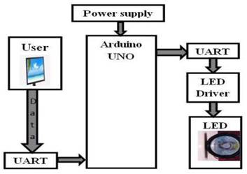
|
Figure 2 Transmitter |
One of the simplest forms of amplitude-shift keying is on-off keying (OOK), which is frequently used in VLC systems. OOK is straightforward to implement and integrate in terms of hardware. In this modulation scheme, a binary '1' is represented by a high voltage level (e.g., 5V), while a binary '0' is represented by a low voltage level (e.g., 0V). In our research, we employ the OOK modulation scheme, where binary '1' is transmitted as a 5V signal, and binary '0' is transmitted as a 0V signal. During demodulation, the 5V signal is mapped to a binary '1', and the 0V signal is mapped to a binary '0'. We focus on the utilization of intensity modulation with direct detection (IM/DD) in VLC systems. Due to the noncoherent nature of LED light, we rely on modulating the instantaneous power of the optical carrier, and the receiver detects only the intensity of the optical wave. We employ on-off keying (OOK) as our chosen modulation scheme, representing binary '1' and '0' with high and low voltage levels, respectively. This simplified modulation scheme is suitable for VLC systems, considering the limitations imposed by the non-coherence of LED light and the hardware constraints of LEDs and photodetectors.
Figure 3
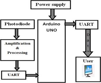
|
Figure 3 Receiver |
4) Turbo Codes: Turbo Encoding: Turbo Codes are powerful error correction codes that employ iterative encoding and decoding techniques. The Turbo encoding process involves the following steps:
• Input Data: The input data stream is divided into blocks, typically referred to as information bits.
• Convolutional Encoding: The information bits are encoded using two or more parallel convolutional encoders. Each encoder generates a redundant bit stream based on the input bits and its internal state. The encoders are typically chosen to have different generator polynomials.
• Interleaving: The redundant bit streams from the parallel encoders are interleaved to spread the errors evenly over the encoded sequence. Interleaving helps to combat burst errors in the channel.
• Concatenation: The interleaved bit streams are concatenated to form the Turbo codeword, which contains the original information bits along with the generated redundant bits.
Figure 4
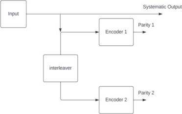
|
Figure 4 Turbo
Encoder. |
5) Turbo Decoding: The Turbo decoding process involves iterative decoding and combines the information from both the systematic and redundant bits. The decoding process can be summarized as follows: • Soft-Input Soft-Output (SISO) Decoding: The received codeword is fed into the Turbo decoder, which consists of two parallel SISO decoders corresponding to the two encoders used in the encoding process. The SISO decoders perform iterative decoding, providing soft-input and soft output information. • Turbo Iterations: The soft-output information from one SISO decoder is passed to the other SISO decoder as an extrinsic information. This iterative exchange of information is repeated multiple times to improve the decoding performance. • Appending the Extrinsic Information: The extrinsic information obtained from the Turbo iterations is appended to the systematic bits of the codeword. This provides enhanced reliability in the decoding process. • Final Decision: After a sufficient number of Turbo iterations, the final decision on each bit is made based on the reliability information obtained from the decoding process. The decoded bits are then output as the estimated original information bits.
Figure 5
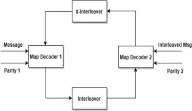
|
Figure 5 Turbo
Decoder |
2.1. Materials
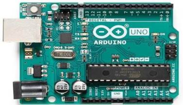
1) Arduino
uno: The Arduino Uno is a microcontroller board based on the ATmega328. It
has 20 digital input/output pins (of which 6 can be used as PWM outputs and 6
can be used as analog inputs), a 16 MHz resonator, a
USB connection, a power jack, an in-circuit system programming (ICSP) header,
and a reset button.
Figure 6
|
Figure 6 Arduino uno |
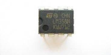
2) IC
LM358: The LM358 is a great, easy-to-use dual-channel op-amp. Op-amps have
so many applications we figured we should probably carry at least one in a DIP
package. LM358 applications include transducer amplifiers, DC gain blocks and
all the conventional op-amp circuits. If you're looking for a good, standard
op-amp the LM358 should fill most of your needs. It can handle a supply of
3-32VDC and source up to 20mA per channel. This op-amp is great if you need to
operate two individual op-amps from a single power supply. It comes in an 8-pin
DIP package.
Figure 7
|
Figure 7 IC LM358 |
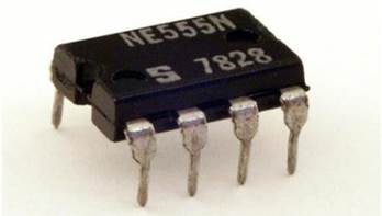
3) 555 TIMER: The 555 timer IC is an integrated circuit (chip) used in a variety of timer, delay, pulse generation, and oscillator applications. Derivatives provide two (556) or four (558) timing circuits in one package. The design was first marketed in 1972 by Signetics.
Figure 8
|
Figure 8 555 Timer |
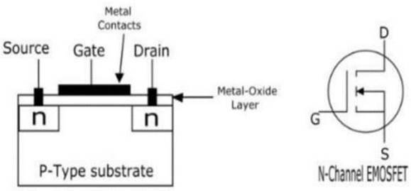
4) N-Channel
MOSFET: The Enhancement Mode Metal Oxide Semiconductor Field Effect
Transistor (EMOSFET) is a three-terminal Device viz. Source (S), Gate (G) and
Drain (D). The EMOSFET is a voltage- controlled device. The EMOSFET can be
operated in the enhancement mode only. By the application of gate–source
voltage (VGS) of proper magnitude and polarity the device can be made operating.
Figure 9
|
Figure 9 N-Channel
MOSFET |
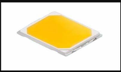
5) LED Array: The purpose of the LEDs in the VLC system is to provide light to be used to transmit data. LEDs accomplish this by turning on which represents a logic 1 and turning off which represents a logic 0. In order to be successful in attaining our goals, we needed to make sure that the LEDs we selected were bright and can switch at a high frequency. Without LED s capable of those features, the transmitting distance and data rate would be small. This would cause the transmission of audio to be difficult, especially with ambient light present.
Figure 10
|
Figure 10 LED Array |
6) Solar Panel: A solar panel is a device which converts sunlight into electricity by using photovoltaic (PV) cells. PV cells are made of materials that generate electrons when exposed to light.
Figure 11

|
Figure 11 Solar Panel |
7) Software
Tools:
• Multisim 14.1
• Matlab
• Arduino IDE
• VISUAL BASICS 6.0
3. RESULTS AND DISCUSSIONS
1) LED
Driver Circuit: This project focuses on designing an LED driver circuit and
implementing it using Multisim, a simulation software. The LED driver circuit
is designed to provide the necessary current and voltage regulation to drive
LEDs effectively. Through Multisim, the circuit design is simulated, allowing
for analysis and optimization before actual hardware implementation. The
project aims to achieve efficient and reliable LED operation by considering
factors such as current limiting, thermal protection, and voltage regulation.
By utilizing Multisim's simulation capabilities, the designed LED driver
circuit can be thoroughly tested and verified before moving to the physical
implementation stage, ensuring a successful and well-optimized LED driving
solution. Jorge (2014)
Figure 12

|
Figure 12 Simulation
of LED Driver Circuit using Multi-Sim |
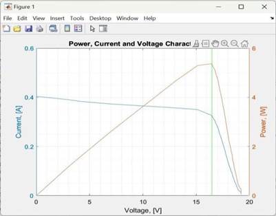
2) Maximum
Power Point Tracking (MPPT Algorithm): We also performed maximum power
point tracking, which will allow us to determine the maximum power at which the
PV cell can be operated and thus maximize the power generated by PV systems.
The algorithms control the voltage to ensure that the system operates at the
power voltage curve's "maximum power point" (or peak voltage). Karunatilaka et al. (2015)
Figure 13
|
Figure 13 MATLAB
Simulation of MPPT Algorithm |
3) Proposed
System:
Figure 14
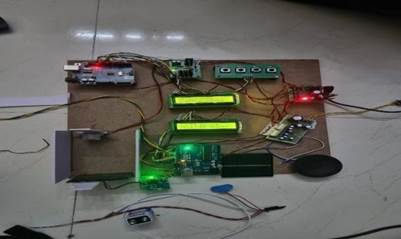
|
Figure 14 Proposed system for Visible Light Communication (VLC) |
For the implementation, the chosen simulation software is Multisim, it is utilized to test and verify the system's performance. Various experiments and simulations were conducted to evaluate the system's behaviour under different scenarios, considering factors such as noise, interference, and channel characteristics. The simulations provided valuable insights into the system's performance and helped fine- tune parameters for optimal results. The implementation phase also involved practical considerations, such as hardware integration and real-time processing capabilities. Careful selection of components, including LEDs and photodetectors, was made to ensure compatibility with the proposed architecture. Additionally, efforts were made to optimize the computational complexity of Turbo Codes for real-time implementation, utilizing techniques such as parallel processing or hardware acceleration. The successful implementation of the proposed system yielded significant findings. Through extensive simulations and experiments, it was observed that the integration of Turbo Codes in VLC systems greatly improved the system's error correction capabilities. The Turbo decoding algorithms effectively mitigated transmission errors, resulting in enhanced reliability and higher data rates. The designed system demonstrated its potential for practical deployment in real world VLC applications, showing promising results in terms of improved performance and efficient data transmission. However, it is essential to acknowledge certain limitations that were identified during the implementation. These include the computational complexity of Turbo Codes and the restricted modulation schemes associated with intensity modulation and direct detection. Future research should aim to address these limitations, focusing on optimizing computational complexity and exploring advanced modulation. Kathirvalavakumar & Palaniappan (2011)
4. CONCLUSIONS AND FUTURE WORK
4.1. Conclusion
In conclusion, this research paper presented the design and implementation of Visible Light Communication (VLC) utilizing Turbo Codes. The proposed system architecture incorporated Turbo encoding and decoding techniques to enhance the reliability and efficiency of data transmission over VLC channels. Through extensive simulations and experiments, it was found that the integration of Turbo Codes in VLC systems significantly improved the error correction capabilities and increased the overall system performance. Lee & Wolf (1989)
However, it is important to acknowledge certain limitations of the system. Firstly, the use of Turbo Codes requires higher computational complexity compared to simpler error correction codes. This can impact the real-time processing capabilities of VLC systems, especially in scenarios with limited processing resources. Additionally, the reliance on intensity modulation with direct detection (IM/DD) in VLC restricts the modulation schemes that can be utilized, limiting the potential for advanced modulation techniques. Further research is needed to address these limitations and explore more efficient encoding and modulation schemes for VLC systems utilizing Turbo Codes. Pathak et al. (2015)
4.2. Future Work
Firstly, efforts can be made to optimize the computational complexity of Turbo Codes in VLC systems. Exploring techniques such as parallel processing or hardware acceleration can help reduce the computational burden and enable real-time implementation of Turbo decoding algorithms. Safavi-Naini & Seberry (1991)
Furthermore, future research should investigate advanced modulation schemes beyond intensity modulation with direct detection (IM/DD) to further enhance the performance of VLC systems. Exploring techniques like coherent detection or hybrid modulation schemes can allow for the modulation of amplitude, phase, and frequency of the optical carrier, enabling more robust and efficient transmission. Investigating the combination of Turbo Codes with these advanced modulation schemes can unlock new opportunities for higher data rates, improved reliability, and enhanced spectral efficiency in VLC systems.
Overall, future work should focus on overcoming the limitations of the current system and expanding the research to explore more advanced techniques, enabling the design and implementation of high- performance VLC systems using Turbo Codes.
CONFLICT OF INTERESTS
None.
ACKNOWLEDGMENTS
None.
REFERENCES
Arnon, S., Barry, J. R., George, K., & Karagiannidis, R. S. (2012). Advanced Optical Wireless Communication System. Cambridge University Press. https://doi.org/10.1017/CBO9780511979187.
Ghassemlooy, Z. (2005). Indoor Optical Wireless Communication Systems and Networks. John Wiley & Sons, Ltd, 18, 191-193.
Hamming, R. (1950). Error Detecting and Error Correcting Codes. Bell System Technical Journal, 29(2), 147-160. https://doi.org/10.1002/j.1538-7305.1950.tb00463.x.
Haykin, S., & Moher, M. (2010). Communication Systems. 5th ed. Hoboken, N.J. : Wiley, 366-393.
Jorge, O. (2014). Guide to Wireless Communications. Boston MA.
Karunatilaka, D., Zafar, F., Kalavally, V., & Parthiban, R. (2015). LED Based Indoor Visible Light Communications : State of the Art. IEEE Communications Surveys & Tutorials, 17(3), 1649-1678. https://doi.org/10.1109/COMST.2015.2417576.
Kathirvalavakumar, T., & Palaniappan, R. (2011). Modified Run Length Encoding Method and Distance Algorithm to Classify Run Length Encoded Binary Data. Communications in Computer and Information Science, 271-280. https://doi.org/10.1007/978-3-642-19263-0_33.
Lee, P., & Wolf, J. (1989). A General Error Correcting Code Construction for Run Length Limited Binary Channels. IEEE Transactions on Information Theory, 35(6), 1330-133. https://doi.org/10.1109/18.45295.
Pathak, P., Feng, X., Hu, P., & Mohapatra, P. (2015). Visible Light Communication, Networking, and Sensing : A Survey, Potential and Challenges. IEEE Communications Surveys & Tutorials, 17(4), 2047-2077. https://doi.org/10.1109/COMST.2015.2476474.
Safavi-Naini, R., & Seberry, J. (1991). Error Correcting Codes for Authentication and Subliminal Channels. IEEE Transactions on Information Theory, 37(1), 13-17. https://doi.org/10.1109/18.61124.
|
|
 This work is licensed under a: Creative Commons Attribution 4.0 International License
© IJETMR 2014-2023. All Rights Reserved.