
|
|
|
|
ADDITIVE MANUFACTURING IN TURBOMACHINERIES
Poonchezhian Vishnu Prakash 1![]()
![]() ,
Dr. P. Jothilakshmi 2
,
Dr. P. Jothilakshmi 2![]()
1 UG Student (Passed out), Department of Manufacturing Engineering, Central Institute of Petrochemicals Engineering and technology, Chennai, India
2 Professor, Department of ECE, Sri Venkateswara College of
Engineering, Sriperumbudur, India
|
|
|
ABSTRACT |
|
|
The primary
objective of this paper is to discuss the recent advancements of Additive
manufacturing in the field of turbomachinery. The most challenging thing in
real world is fabricating a large turbine or a propeller with short
production run, less tool investment cost and finally less carbon print.
Additive manufacturing not only achieves this but also provide several
advantages over conventional machining process. This paper aims to elaborate
current trends in additive manufacturing methods, history of AM, its
advantages and challenges and AM’s role in making the turbomachinery
manufacturing easier. |
|||
|
Received 03 April 2022 Accepted 05 May 2022 Published 24 May 2022 Corresponding Author Dr. P.
Jothilakshmi, DOI 10.29121/ijetmr.v9.i5.2022.1148 Funding: This research
received no specific grant from any funding agency in the public, commercial,
or not-for-profit sectors. Copyright: © 2022 The
Author(s). This work is licensed under a Creative Commons
Attribution 4.0 International License. With the
license CC-BY, authors retain the copyright, allowing anyone to download,
reuse, re-print, modify, distribute, and/or copy their contribution. The work
must be properly attributed to its author.
|
|||
|
Keywords: Additive Manufacturing,
Turbomachinery, Sustainable Manufacturing, Selective Laser Melting, Turbine,
3d-Printing |
|||


1. INTRODUCTION
Turbomachinery plays a major role in our day-to-day life, from aiding in producing electricity to pumping water for our homes. Turbomachines basically work on the principle of energy conversion, either converting mechanical energy into fluid energy (e.g., Pumps, compressors) or converting fluid energy into mechanical energy (E.g., Turbines). Turbomachines could be classified based on the flow of fluid into the energy system and the environment in which the turbomachine is placed. Based on the flow of It has always been a goal for energy system designers, to maximize the efficiency of the energy cultivation process, with less time spent in maintaining it. Also, additive manufacturing allows engineers to design novel orifice shapes and mixing chambers, thus improvising fuel and air mixtures for optimal performance and efficiency.
"Additive Manufacturing" (AM) is a modern-day layer-based automated manufacturing technique that produces scaled 3-dimensional objects directly from 3D-CAD data, eliminating the need for part-dependent tools. Ever since Charles W. Hull made the breakthrough in additive manufacturing field in 1983 by fabricating a teacup from his self-built SLA apparatus Jiménez et al. (2019), a lot of different AM techniques have been developed and are in practice today. AM may also incorporate additional functionality into components, such as interior cooling channels, thermowells and produce very complicated geometries that would be impossible or extremely difficult to do with traditional techniques. Unlike the conventional machining and metallurgy processes, AM eliminates the necessity for tools and casting patterns.
AM Technology was earlier called Rapid Prototyping (RP). Until 2009, a lot of terminologies were used in the place of AM. Then it was decided by the ASTM F42 technical committee members to formally adopt the term ‘AM’ Gebhardt (2011). In spite of ASTM F42’s guidelines, terms like 3D Printing, additive fabrication are still being used by the scientific and engineering community. Unlike rapid prototyping, rapid manufacturing (RM) and rapid tooling (RT) aim to create long-lasting items. RM is focused with the manufacture of protracted consistent components (such as a dental implant), whereas RT is concerned with the manufacture of protracted consistent tools (such as a plastic injection mould insert).
For a lot of years, turbomachinery components have been manufactured using the traditional and conventional manufacturing methods. The conventional manufacturing methods, which are often referred to as subtractive manufacturing methods, have been in practice for a lot of years in the human history. Subtractive manufacturing refers to a variety of controlled machining and material removal methods that begin with solid stocks of various shapes that undergo further material removal by cutting, milling, drilling, and grinding, in order to be congruent with the intended design. These processes are either manual or automated. An example for a manual subtractive manufacturing method would be a typical lathe machine and an example of automated subtractive machining would be a CNC Lathe machine.
In today’s world, the manufacturing and maintenance of turbine blades and components is a very tedious task. Through conventional machining methods, a lot of time and work are needed to be put, in order to produce the desired design of the turbomachinery component. And to overcome the hurdles put forth by the traditional machining, the turbomachinery industry has been taking a turn towards additive manufacturing and related methods.
2. METHODS
Turbomachinery components are mainly made from metal. Hence, an AM processes that are dedicated to manufacture metal are required. Metal additive manufacturing employs a variety of processes (powder bed fusion, directed energy deposition, and binder jetting). The majority of metal additive manufacturing processes use a concentrated heat source, such as a laser or an electron beam, to melt powder or wire. Surface roughness/waviness, dimensional tolerance, microstructure, porosity, hardness, and residual stress are all variables that impact the quality of 3D-printed components. There are seven different classifications of AM namely,
· Binder jetting
· Direct Metal Deposition (DMD)
· Powder bed fusion (PBF)
· Material Extrusion
· Sheet lamination
· VAT Polymerization
· Material jetting
The widest used AM technologies for metal are Selective Laser Melting and Direct Energy Deposition, which are known to generate near-net products with 99% relative density. In spite of that, Fused deposition modelling (FDM) of metal is also being considered in manufacturing metallic components. These three methods are briefly discussed as below.
2.1. SELECTIVE LASER MELTING (SLM)
Selective Laser Melting (SLM) is one of the widest used AM technologies for manufacturing turbine components. SLM is a powder bed fusion process. SLM focuses mainly on manufacturing metallic products. SLM is a rapid prototyping, 3D printing, or Additive Manufacturing (AM) technology that selectively melts and fuses metallic powders on a powder bed using a strong intensity laser. The SLM method is known by a lot of names such as direct selective laser sintering, Laser using, and direct metal laser sintering, and it has been shown to generate near net-shape objects with a relative density of 99.9%. SLM now can treat a wide range of metallic materials, including copper, Aluminium, and Tungsten, thanks to recent breakthroughs in fibre optics and high-power lasers. Similarly, SLM of ceramic and composite materials has opened up new research potential Goutianos (2017).
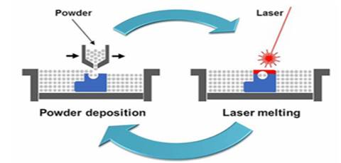
SLM has been enhanced to perform repairs on damaged components in addition to direct manufacture. Scanning Laser Epitaxy (SLE) was developed by Georgia Tech's Direct Digital Manufacturing Lab for additive repair of nickel-based alloys CMSX-4,5,6 Rene 80,7, and IN100. 8 SLE requires a minimal amount of powder for repair, sufficient to cover the damaged part's surface with a powder layer of up to 2 mm. The powder material is then melted with a high-powered Nd: YAG laser Yap et al. (2015), covering fractures and holes in the affected component. A simple diagram explaining the SLM process is shown in Figure 1
Figure 1
|
Figure 1 The SLM process has been explained using a simple diagram. SLM Solutions (2022) |
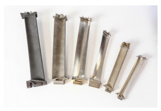
A lot of different components, ranging from large parts such as gas turbine engines, turbine blades to small parts such as nozzle guides could be manufactured through selective laser melting process. Some of the widest used material in SLM for manufacturing turbomachinery components are Inconel alloys, Ni-based super alloys, and Ti-Al alloys. We shall discuss the materials in the following passages.
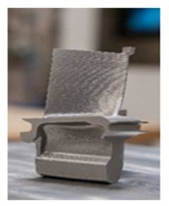
Figure 2
|
Figure 2 3d printed turbine blades made using SLM for aerospace applications by Avio-Aero Kellner (2018) |
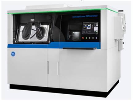
Figure 3
|
Figure 3 GE Additive’s M2 Series 5 SLM machine. GE Additive (2022) |
2.2. ELECTRON BEAM MELTING (EBM)
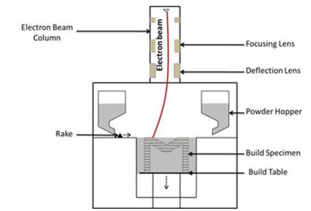
Electron beam melting is an AM process which is very much similar to the Selective laser melting process. The difference between SLM and EBM is that in SLM, a laser beam is used and in EBM an electron beam is used. EBM is carried out in a controlled environment, where a high-energy electron beam is used to melt and fuse the metal powder spread across the platform. EBM creates high-strength components that take use of the natural qualities of the metals utilized in the process, minimizing impurities that might occur when casting metals or using other production processes. Components for aerospace, automotive, defence, petrochemical, and medical industries are manufactured using EBM. Figure 4 shows a schematic diagram of EBM Suard et al. (2014).
Arcam teamed up with Chalmers University of Technology in Gothenburg to file a patent application on EBM concepts in 1993. The method was designed with the aim of melting an electrically conductive powder layer after layer using an electric beam to create 3D things. Arcam AB was established in 1997, and it has since proceeded to develop and market EBM printing. In 2014, engineers at Avio Aero, an Italian aerospace firm which is a part of General Electric (GE), used EBM for manufacturing light-weight metal blades for jet engine turbines. The blades were made from an alloy called Titanium Aluminide Chen and Li (2019). Figure 5 shows GE additive’s Spectra H EBM machine GE Additive (2022).
Figure 4
|
Figure 4 A schematic diagram showing the EBM process in detail. Suard et al. (2014) |
Figure 5
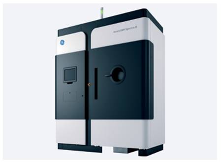
|
Figure 5 GE Additive’s Spectra H EBM machine. GE Additive (2022) |
EBM costs less than SLM and has also high productivity compared to it. When opposed to a laser, using an electron beam as an energy source to melt metal powder has several benefits. The electron's ability to reach deep into the material and uniformly melt the powder particles is a significant benefit. This allows highly reflective metals to be melted without the risk of vaporising the particle's surface before melting the core. Furthermore, the EBM method enables the use of bigger powder particles and the formation of a thicker layer, resulting in easier and safer powder handling as well as a more productive process. Powder with bigger particles has a price difference of up to 50%, which has a major influence on component cost in volume production. Also, EBM is a hot process, thus eliminating the need for further heat treatments.
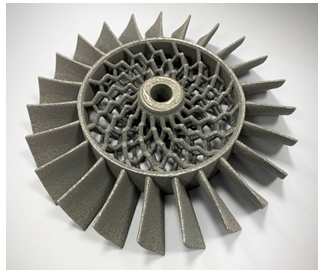
Figure 6
|
Figure 6 An impeller
made with EBM by Wayland Additive ADS Advance (2020) |
2.3. BINDER JETTING
Binder jetting is a process of additive manufacturing in which powdered material is dispersed into a layer and selectively linked into the desired layer form with a binder, which is usually a polymeric liquid. The layers of the print are bound together as the build advances, resulting in a powder box with binder organised in the 3D shape of the desired component geometry. The box can then be heated to cure or "set" the binder if necessary, and the printed parts can then be removed from the powder bed. The printed parts are then treated to a post-process such as sintering or infiltration to acquire desired mechanical properties.
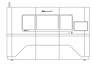
Binder jetting technique was first created at the Massachusetts Institute of Technology (MIT) and patented in 1993 by Emanuel Sachs, who used a gypsum-like powder and a glycerine/water binder applied by thermal bubble inkjet printheads to create the process Mostafaei et al. (2021). Recently, General Electric (GE) adopted binder jetting technology to create moulds for their wind turbines. Creating moulds through binder jetting process proved to be efficient as the time taken to create a mould by traditional process was 10 weeks, while through binder jetting it was only two weeks. Figure 7 shows ExOne’s X160pro, the world’s largest binder jetting machine for manufacturing metals, ceramics, and polymers X-Series (2022).
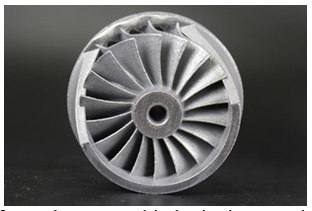
Components made through Binder jetting process usually have good mechanical properties due to the infiltration process. But due to the poor fusion of grains during the process, binder jetting falls behind SLM and EBM in terms of mechanical properties. Metals such as Titanium Aluminides, Nickel based alloys and Stainless steel can be used in binder jetting process. Aluminium is a very difficult metal to sinter, hence making it difficult to use in binder jetting. Binder Jetting has set its foot on almost many industries such as aerospace, automobile, jewelleries, etc. More than a few companies such as GE, Exone, Sculpteo and Voxeljet provide binder jetting solutions. In 2021, ExOne was acquired by Desktop metal. Figure 8 shows an impeller made from ultra-porous binder jetting powders by Uniformity labs and Desktop metal Additive Manufacturing (2022).
Figure 7
|
Figure
7 ExOne’s
X160pro, the world’s largest binder jetting machine for manufacturing metals,
ceramics, and polymers X-Series (2022) |
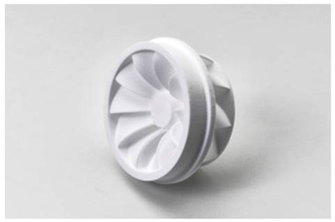
Figure 8
|
Figure
8 An impeller made from
ultra-porous binder jetting powders by Uniformity labs and Desktop metal Additive Manufacturing (2022) |
2.4. FUSED DEPOSITION MODELING (FDM)
Fused deposition modelling is different than all of the AM methods mentioned above. It is the most common type of AM and is extensively used. In the FDM process, the material which is either in filament or pellet form is extruded through a nozzle, that traces the part’s CAD model layer by layer. In case of pellets, they ae fed through a hopper to the nozzle. Resistive heaters in the nozzle hold the plastic at a temperature just above melting point, allowing it to flow smoothly through the nozzle and build the layer. After squeezed out of the nozzle, the plastic hardens and adheres to the layer below. ABS, polyamide, polycarbonate, polyethylene, polypropylene, and investment casting wax are among the materials available. Among them ABS, has good mechanical properties and is widely used in the manufacture of FDM based wind turbine blades Sivamani et al. (2020).
Recently, FDM process is widely used to manufacture propeller blades for Autonomous underwater vehicles (AUV’s) Toleos et al. (2020). Also, FDM is used to make wind turbines Bassett et al. (2015), impellers and propellers for small and compact turbomachines. With the increase in desktop 3d printers, the demand for metal and ceramic 3d printing has drastically increased over the years. Several popular FDM manufacturers such as Ultimaker, BCN3D and MakerBot have released metal filament fibres with specially adapted nozzles. With Raise3D and 3DGence releasing FDM Metal printers in 2022, we can expect FDM metal printing to be implemented on a large scale.
Figure 9
|
Figure 9 Casting core
for impeller made from PMMA (Polymethyl Methacrylate) through FDM by Voxeljet
V-Xylite (2022) |
3. MATERIALS
3.1. NICKEL BASED SUPER ALLOYS
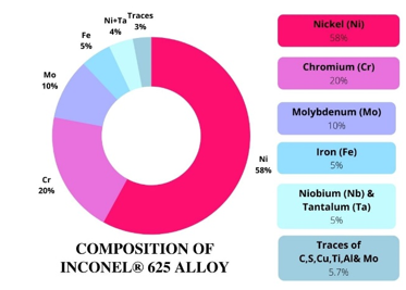
Ni based alloys have known to exhibit greater strength and mechanical properties. Due to this, they have been a favourite choice in the AM industry, to make mechanical components. Examples of Ni-based alloys used in AM are Inconel alloys and Inconel is a high-strength nickel-chromium-molybdenum alloy with excellent temperature and corrosion resistance. With Nickel being predominant element, Chromium, Molybdenum, Niobium, Iron, Tantalum, Cobalt, with traces of Manganese, Silicon, Aluminium, and Titanium make up this superalloy. Some of the frequently used Inconel alloys in additive manufacturing of turbomachinery components are IN-625, IN-718 and IN-738.
Figure 10
|
Figure 10 A donut
chart showing the composition of Inconel 625 alloy |
Due to their high strength and corrosion resistance, Inconel based components are mainly preferred in areas where the components are subjected to high-pressure as well as being in direct contact with fluids. Siemens recently developed improved turbine blades that will be manufactured using DMLS (Direct Metal Laser Sintering) technology. The turbine blades were 3D printed using a nickel super-alloy powder on an Eosint DMLS machine in partnership with Material Solutions Sinha et al. (2022).
Figure 11
|
Figure 11 A 3d printed
gas turbine blade for extreme power plant operating conditions, manufactured
by Siemens through SLM using a Ni based super alloy Goehrke (2022) |
3.2. TITANIUM ALUMINIDES
Intermetallic titanium aluminides are one of the few new material classes with the potential to be employed in high-temperature structural applications where strength and stiffness are crucial. Nevertheless, titanium aluminides must combine a wide range of mechanical property capacities in order to successfully replace the heavier nickel-base superalloys now in use.
A writer places in the appendices additional information that supports or illustrates points in the paper. Items in the appendices allow the reader to go deeper or gain a clearer view of what is being said in the main text.
Titanium aluminides are one of the materials, which is widely used and considered as a replacement for nickel based super alloys. Since 2006, when TiAl blades were initially incorporated into the low-pressure turbine (LPT) of GEnx engines, it has been more than a decade Kim and Kim (2018). The major advantage that titanium aluminide provides is that it is lightweight and has high modulus and creep strength when compared to Ni based super alloys. Due to this, TiAl has found variety of applications in the aviation and energy industry Pitot et al. (2021). And now, through additive manufacturing processes such as SLM, Laser metal deposition and EBM, it is possible to produce turbomachinery components made of TiAl.
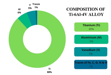
TiAl generally comprises of Titanium (about 42%), Aluminium (49%) and traces (0.1% - 10%) of Nb, Cr, V, Ta, Mo, Zr, W, Si, C, and B [AMT]. The most commonly used TiAl alloy in AM is Ti6Al4V. In recent days, TiAl based compressor blades and shrouds, impellers, blade retainers and turbine dampers are being developed by manufacturing giants such as Pratt & Whitney, Scema and Turbomeca.
Figure 12
|
Figure 12 A donut
chart showing the composition of Ti- 6Al-4V alloy |
4. THE AM PROCESS
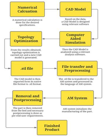
Usually, a product undergoes several steps while being Additive manufactured. Initially a numerical calculation of the desired specifications is worked out and the required parameters are calculated. Then the desired material is chosen and compared with other available materials in the market. Based on all the data available in the hand, a CAD model is generated using relevant modelling software Introduction to Additive Manufacturing (2020). Figure 13 shows a simple flowchart explaining the AM process.
Then, the CAD model is analysed in a computer, using specific simulation software such as ANSYS, Autodesk Nastran, etc. And the most important step comes next, which is topology optimization. From the results obtained from the computer simulation, the CAD model is again revised, and a new model is generated Meli et al. (2019).
Generally, the default file format for an AM system is. stl (Standard Triangle Language). The CAD model, which is in its native state, must be converted to a .stl file, before it is fed into the AM system. Then, the file is transferred, and pre-processing work is carried out inside the AM system. After confirming whether the process is ready to be carried out, the bed of the AM system must be prepared
And now, the AM process is carried out in the bed or substrate, in which layer after layer the component is produced. After this, the component needs to be removed from the substrate. Specific removal techniques exist for different AM processes. And now, the AM process is carried out in the bed or substrate, in which layer after layer the component is produced. After this, the component needs to be removed from the substrate. Specific removal techniques exist for different AM processes.
Figure 13
|
Figure
13 Flowchart explaining the steps involved in AM
process |
5. ADVANTAGES
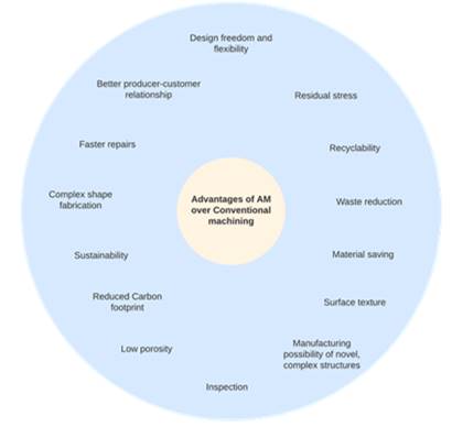
AM offers a lot of advantages over traditional manufacturing, when it comes to production of turbomachinery components. AM is considered as a eco-friendly manufacturing process and is being adopted by several industries around the world. The advantages of AM processes include Sustainability and low carbon footprint, faster manufacturing cycle, design freedom, accuracy and efficiency, reduced lead time and removing tooling needs. Figure 14 shows the advantages of AM over conventional manufacturing. Each advantage of AM when implemented are as follows.
· Sustainability
· Faster manufacturing cycle
· Design freedom
· Accuracy and efficiency
· Reduced lead time
· Remove tooling needs
· Faster repairs
5.1. SUSTAINABILITY IN ADDITIVE MANUFACTURING
AM has evolved over the years to become a highly sustainable process as AM utilizes very little material and generates minimal waste compared to traditional processes. Also, AM implements generative design, which mainly focuses on analysing and reducing material in unnecessary areas. In 2019, the non-profit AMGTA (Additive Manufacturing Green Trade Association) was founded, demonstrating that important companies in additive manufacturing were interested in making a statement in the cause of sustainability. The AMGTA wants to enhance public and industrial knowledge of 3D printing as a viable alternative to traditional production processes.
5.2. REDUCED LEAD TIME
AM gains a huge advantage over conventional manufacturing processes by eliminating the need for casting. Usually, large turbomachinery components such as a turbine or a propeller are made through casting and then machining them by appropriate material removal processes. And due to this, the lead time of traditional manufacturing is always larger than that of AM, since AM doesn’t require any additional process prior to it.
5.3. DESIGN FREEDOM
AM allows for the creation of complex and detailed geometries without the limitations imposed by traditional production methods. Turbomachinery components with novel and complex geometries can be designed and manufactured through AM. AM will become a more common and feasible engineering and commercial solution as technology progresses and the cost of 3D printed items continues to plummet.
5.4. FASTER MANUFACTURING CYCLE
The mean time taken by a component to go through all the manufacturing facilities during a process is called the cycle time (CT). Both large- and small-scale industries can have tangible financial benefits by lowering cycle times. Also, shorter cycle time aids an industry to get the market and win over competitors. Since manufacturing of turbomachinery components usually have a longer cycle time, introduction of AM is a huge advantage when compared to traditional manufacturing processes. Companies like Sulzer have come up with ideal approaches, like combining additive and subtractive manufacturing in one tool. Sulzer combined metal AM and machining into a hybrid process, in order to manufacture closed impellers quickly.
5.5. ACCURACY AND EFFICIENCY
The overall accuracy of the machine has a big impact on the final dimensional accuracy. AM machines generally have high accuracy, with material jetting machines having the most. Also, since the material used in AM process is directly converted into the final product, there is no scrap produced during the process, making AM highly efficient.
5.6. REMOVE TOOLING NEEDS
AM machines eliminate the biggest challenge in manufacturing turbomachinery parts, i.e., tooling needs and compensation. Almost any kind of geometry can be produced through additive manufacturing, ranging from small too big.
5.7. FASTER REPAIRS
Another advantage of 3D printing is that it can fix worn-out components more quickly than traditional repair methods. SLM (Selective Laser Melting) and LMD (Laser Melting and Deposition) are two technologies that may be used to repair items. Siemens has developed a method to repair damaged components using AM Anner (2022). The manufacturing giant has developed a special SLM machine for this purpose. An example of the process would be burner tip repair procedure. SLM repair required very minimal area of the burner tip to be replaced and repaired
Following the removal of the damaged region, the complete burner is placed in the SLM system, where a camera determines the precise 3D location of the burner tip face and projects a CAD model onto it. Then, layer by layer, a new tip is created. According to Siemens, this strategy allows them to cut maintenance time in half. Siemens has restored over 2000 burners after using SLM for repair in 2013.
Figure 14
|
Figure
14 Advantages of Additive
manufacturing over traditional methods |
6. CHALLENGES IN AM
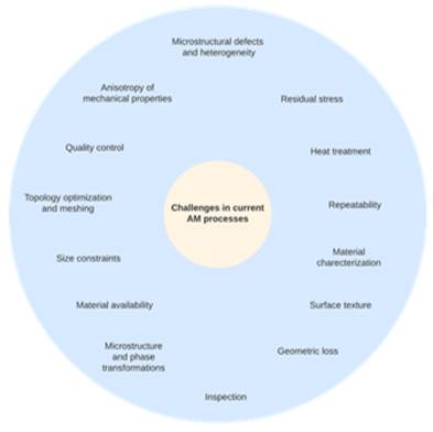
Several challenges hinder AM technology from adopting it everywhere. The benefits stated are ones that have been proven in specific applications. However, because AM technologies for direct production are still in their infancy, their widespread acceptance and realisation of these benefits is dependent on overcoming the considerable hurdles mentioned. Figure 15 shows all the challenges in implementing AM. Such challenges in AM include GE Additive (2022)
· Size and geometrical restrictions
· Material availability
· Quality control and inspection
· Microstructure
· Mechanical properties
· Post-processing techniques
6.1. SIZE AND GEOMETRICAL RESTRICTIONS
Another current AM technology possesses a size constraint such that it is difficult to manufacture products under the volume of 500mm3. Srinivasan (2021). All components that are desired to be additive manufactured are first designed as a CAD model and then fed into the system as an STL file. The STL file plays a major role in determining the surface texture and smoothness of the output. Consider a product such as an impeller is to be made through AM. An impeller generally comprises of several curves and splines in its geometry. Generally, a CAD model that is converted into an STL file is made of several polygons. It is the number of polygons available that reflect the surface texture. Higher number of polygons tend to produce good surface texture and curves and vice versa. A minimum wall thickness should also be considered when a product is manufactured through AM, though it can vary for different AM processes.
6.2. MATERIAL AVAILABILITY
Very few materials are available for metal AM production, even though several powder manufacturers are available. AM is a layer-by-layer fabrication process and in this case, metal powder layers are stacked on to one another through the process of melting, which is similar to welding. Since welding of aerospace alloys is an onerous task, it takes time to go through the properties of the available material and certifying it for AM. Also, getting new chemistry of materials and analysing its properties to make it amenable for AM is a time-consuming process.
AM machines eliminate the biggest challenge in manufacturing turbomachinery parts, i.e., tooling needs and compensation. Almost any kind of geometry can be produced through additive manufacturing, ranging from small too big.
6.3. QUALITY CONTROL AND INSPECTION
Since AM is a modern technology, current inspection techniques for AM are somewhat underdeveloped and costly when compared to conventional machining processes. It will be a tedious task starting inspection from a coupon level testing to an assembly level. Also, a good knowledge of proper inspection techniques is also required. Even a small amount of crack could lead to the fracture and failure of a part such as a turbine blade and engine. To guarantee a short turnaround time for establishing solid quality control, in-situ process monitoring for layer-wise flaws or part-wise quality is important, ideally with reliable closed-loop feedback systems. And due to this, quality control techniques for AM processes still need a lot of improvement and development.
6.4. MICROSTRUCTURE
Turbomachinery components are made from a lot of different alloys and not every alloy can be used in AM processes. Because the melting and solidification dynamics during the printing process result in undesirable microstructures with big columnar grains and periodic fissures, the great majority of over 1000s of alloys used in turbo machinery today cannot be manufactured through AM. Depending on the thermal gradients during the rapid solidification process, it is normal to predict a directed structure with elongated or columnar grains when using the AM method. The manufactured sample will then have a texture that runs parallel to the build direction. Also, due to the rapid solidification process, many alloys such as TiAl and Inconel form non-equilibrium phases ADS Advance (2020). TiAl alloys tend to form a martensite phase during DED or LBM and Inconel alloys were found to exhibit heterogeneity in phases of build height.
6.5. MECHANICAL PROPERTIES
Anisotropy is the major challenge while implementing AM for large components. Factors contributing to anisotropy are such that: build and crystallographic orientation, micro-structure heterogeneity and defects, residual stresses, and texture. The mechanical property anisotropy of several turbine engine materials such as Ti6Al4V, IN718, IN625, Hastelloy X, MM247LC, and AlSi10Mg has been reported in several studies Srinivasan (2021).
Figure 15
|
Figure
15 Advantages of Additive
manufacturing over traditional methods |
6.6. MECHANICAL PROPERTIES
Even though AM is an advanced process and possesses several advantages over conventional machining processes, process-specific post-processing techniques are very less and need to be developed over the future. Post processing determines the surface finish and roughness of a component.
7. CONCLUSION
This paper provides the current trend of additive manufacturing (AM0 in the turbomachinery industry. The AM process has been explained and the methods and materials implemented has also been explained in detail. Also, the advantages and challenges in implementing AM in turbomachinery industries has been explained. AM is a constantly developing process and the future is yet to bring lot of new and innovative methods for AM. Several industries have already started adopting AM to produce improvised results. In the coming days, AM will co-exist with conventional machining process, with AM dominating.
CONFLICT OF INTERESTS
None.
ACKNOWLEDGMENTS
None.
REFERENCES
ADS Advance (2020). Wayland Additive develops new PBF Process.
Additive Manufacturing (2022). Desktop Metal, Uniformity Labs Collaborate on Low-Porosity Binder Jetting Powders
Anner, A. (2022). Additive manufacturing revolution for gas turbines, Siemens Energy Global.
Bassett, K. Carriveau, R. & Ting, D. S. K. (2015). 3D printed wind turbines part 1 : Design considerations and rapid manufacture potential. Sustainable Energy Technologies and Assessments, 11. https://doi.org/10.1016/j.seta.2015.01.002
Chen, W. & Li, Z. (2019). Additive manufacturing of titanium aluminides. Additive Manufacturing for the Aerospace Industry, 235-263. https://doi.org/10.1016/B978-0-12-814062-8.00013-3
GE Additive (2022). Arcam EBM_Spectra H_Machine.
GE Additive (2022). Concept Laser_M2 Series 5_Machine.
Gebhardt, A. (2011). Understanding Additive Manufacturing. In Understanding Additive Manufacturing (p. I-IX). Carl Hanser Verlag GmbH &, Co. KG. https://doi.org/10.3139/9783446431621.fm
Goehrke, S.A. (2022). Siemens Advancing Additive Manufacturing: Exclusive Interview, Part One - Leveraging Expertise.
Goutianos, S. (2017). Selective Laser Melting of Hot Gas Turbine Components : Materials, Design and Manufacturing Aspects. IOP Conference Series: Materials Science and Engineering, 219(1). https://doi.org/10.1088/1757-899X/219/1/012022
Introduction to Additive Manufacturing. (2020). In Additive Manufacturing World Scientific. 1-18. https://doi.org/10.1142/9789811224829_0001
Jiménez, M. Romero, L. Domínguez, I. A. Espinosa, M. del M. & Domínguez, M. (2019). Additive Manufacturing Technologies : An Overview about 3D Printing Methods and Future Prospects. Complexity, 2019, 1-30. https://doi.org/10.1155/2019/9656938
Kellner, T. (2018). The Blade Runners: This Factory Is 3D Printing Turbine Parts For The World's Largest Jet Engine.
Kim, Y. W. & Kim, S. L. (2018). Advances in Gammalloy Materials-Processes-Application Technology: Successes, Dilemmas, and Future. 70(4), 553-560. https://doi.org/10.1007/s11837-018-2747-x
Meli, E. Rindi, A. Ridolfi, A. Furferi, R. Buonamici, F. Iurisci, G. Corbò, S. & Cangioli, F. (2019). Design and production of innovative turbomachinery components via topology optimization and additive manufacturing. International Journal of Rotating Machinery. https://doi.org/10.1155/2019/9546831
Mostafaei, A. Elliott, A. M. Barnes, J. E. Li, F. Tan, W. Cramer, C. L. Nandwana, P. & Chmielus, M. (2021). Binder jet 3D printing-Process parameters, materials, properties, modeling, and challenges. Progress in Materials Science, 119, 100707. https://doi.org/10.1016/j.pmatsci.2020.100707
Pitot, J. Lopez, E. Leary, M. Berto, F. & du Plessis, A. (2021). Metal additive manufacturing in aerospace: A review. Materials & Design, 209. https://doi.org/10.1016/j.matdes.2021.110008
SLM Solutions (2022). Metal Additive Manufacturing for Production.
Sinha, A. Swain, B. Behera, A. Mallick, P. Samal, S. K. Vishwanatha, H. M. & Behera, A. (2022). A Review on the Processing of Aero-Turbine Blade Using 3D Print Techniques. Journal of Manufacturing and Materials Processing, 6(1). https://doi.org/10.3390/jmmp6010016
Sivamani, S. Nadarajan, M. Kameshwaran, R. Bhatt, C. D. Premkumar, M. T. & Hariram, V. (2020). Analysis of cross axis wind turbine blades designed and manufactured by FDM based additive manufacturing. Materials https://doi.org/10.1016/j.matpr.2020.05.438
Srinivasan, D. (2021). Challenges in Qualifying Additive Manufacturing for Turbine Components: A Review. Transactions of the Indian Institute of Metals, 74. https://doi.org/10.1007/s12666-021-02199-5
Suard, M. Lhuissier, P. Dendievel, R. Blandin, J.-J. Vignat, F. & Villeneuve, F. (2014). Towards stiffness prediction of cellular structures made by electron beam melting (EBM). Powder Metallurgy, 57(3), 190-195. https://doi.org/10.1179/1743290114Y.0000000093
Toleos, L. R. Luna, N. J. A. B. D. Manuel, M. C. E. Chua, J. M. R. Sangalang, E. M. A. & So, P. C. (2020). Feasibility study for fused deposition modeling (FDM) 3D-printed propellers for unmanned aerial vehicles. International Journal of Mechanical Engineering and Robotics Research, 9(4), 548-558. https://doi.org/10.18178/ijmerr.9.4.548-558
V-Xeliet (2022). PMMA 3D Printing Investment Casting vs SLA & Lost Wax 3D Printing.
X-Series (2022). Desktop Metal. https://www.desktopmetal.com/products/xseries
Yap, C. Y. Chua, C. K. Dong, Z. L. Liu, Z. H. Zhang, D. Q. Loh, L. E. & Sing, S. L. (2015). Review of selective laser melting: Materials and applications. Applied Physics Reviews, 2(4). https://doi.org/10.1063/1.4935926
|
|
 This work is licensed under a: Creative Commons Attribution 4.0 International License
© IJETMR 2014-2022. All Rights Reserved.